Nissan Maxima Service and Repair Manual: Power supply and ground circuit
A/C AUTO AMP.
A/C AUTO AMP.: Description
COMPONENT DESCRIPTION
A/C Auto Amp. (Air Conditioner Automatic Amplifier) The A/C auto amp. (1) has a built-in microcomputer that processes information sent from various sensors needed for air conditioner operation. The air mix door motor(s), the mode door motor, the intake door motor, the blower motor and the compressor are then controlled.
When the various switches and temperature control dial are operated, data is input to the A/C auto amp. from the AV control unit using CAN communication.
The A/C auto amp. is operated with control mechanisms. Signals from various switches and Potentio Temperature Control (PTC) are directly entered into the A/C auto amp.

Power Supply and Ground Circuit for A/C Auto Amp.

A/C AUTO AMP.: Component Function Check
1.CHECK OPERATION
- Press the AUTO switch, and then check that "AUTO" is shown on the display.
- Operate the temperature control dial (driver side). Check that the fan speed or outlet changes. (The discharge air temperature or fan speed varies depending on the ambient temperature, in-vehicle temperature, and temperature setting.)
A/C AUTO AMP.: Diagnosis Procedure
1.CHECK FOR AUDIO DTCS WITH CONSULT
Using CONSULT, perform "SELF-DIAGNOSIS RESULTS" of MULTI AV.
2.CHECK A/C AUTO AMP. POWER SUPPLY

- Turn ignition switch OFF.
- Disconnect the A/C auto amp. connector.
- Turn ignition switch ON.
- Check voltage between A/C auto amp. harness connector M37 terminal 17, 20, 40 and ground.

3.CHECK FUSE
Check 10A fuses [Nos. 3, 6 and 17, located in the fuse block (J/B)].
4.CHECK A/C AUTO AMP. GROUND CIRCUIT
- Turn ignition switch OFF.
- Check continuity between A/C auto amp. harness connector M37 terminals 19, 39 and ground.

19, 39 - Ground: Continuity should exist.
A/C AND AV SWITCH ASSEMBLY
A/C AND AV SWITCH ASSEMBLY: Component Function Check
1.CHECK OPERATION
- Press the AUTO switch, and then check that "AUTO" is shown on the display.
- Operate the temperature control dial (driver side). Check that the fan speed or outlet changes. (The discharge air temperature or fan speed varies depending on the ambient temperature, in-vehicle temperature, and temperature setting.)
A/C AND AV SWITCH ASSEMBLY: Diagnosis Procedure
1.CHECK FOR AUDIO DTCS WITH CONSULT
Using CONSULT, perform "SELF-DIAGNOSIS RESULTS" of MULTI AV.
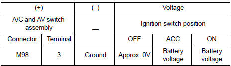
2.CHECK A/C AND AV SWITCH ASSEMBLY POWER SUPPLY

- Disconnect the A/C and AV switch assembly connector.
- Check voltage between A/C and AV switch assembly harness connector M98 terminal 3 and ground.
3.CHECK FUSE
Check 10A fuse [No.17, located in the fuse block (J/B)].
4.CHECK A/C AND AV SWITCH ASSEMBLY GROUND CIRCUIT
- Turn ignition switch OFF.
- Check continuity between A/C and AV switch assembly harness connector M98 terminal 1 and ground.

1 - Ground: Continuity should exist.
 Magnet clutch
Description
SYSTEM DESCRIPTION
A/C auto amp. controls A/C compressor operation by ambient temperature and
signal from ECM.
Low Temperature Protection Control
A/C auto amp. will turn the A/ ...
 ECU diagnosis information
A/C AUTO AMP
Reference Value
VALUES ON THE DIAGNOSIS TOOL
CONSULT MONITOR ITEM
A/C AUTO AMP. HARNESS CONNECTOR TERMINAL LAYOUT
TERMINALS AND REFERENCE VALUES FOR A/C AUTO AMP.
Fa ...
Other materials:
Main line between ADP and DLC circuit
Diagnosis Procedure
1.CHECK CONNECTOR
Turn the ignition switch OFF.
Disconnect the battery cable from the negative terminal.
Check the following terminals and connectors for damage, bend and
loose connection (connector side
and harness side).
Harness connector B1
Harness connect ...
Removal and installation
GENERATOR
Exploded View
-3 Tightening order
Generator
B terminal nut
Generator bracket
Front
Removal and Installation
REMOVAL
Remove hoodledge covers (LH/RH).
Remove cooling fan assembly. Refer to CO-16, "Removal and
Installation".
Remove the A/C compre ...
P0102, P0103 MAF sensor
Description
The mass air flow sensor (1) is placed in the stream of intake air. It
measures the intake flow rate by measuring a part of the entire
intake flow. The mass air flow sensor controls the temperature of the
hot wire to a certain amount. The heat generated by the hot wire is
re ...
Nissan Maxima Owners Manual
- Illustrated table of contents
- Safety-Seats, seat belts and supplemental restraint system
- Instruments and controls
- Pre-driving checks and adjustments
- Monitor, climate, audio, phone and voice recognition systems
- Starting and driving
- In case of emergency
- Appearance and care
- Do-it-yourself
- Maintenance and schedules
- Technical and consumer information
Nissan Maxima Service and Repair Manual

0.006