Nissan Maxima Service and Repair Manual: Compressor control function
Description
PRINCIPLE OF OPERATION
A/C compressor is not activated.
Functional circuit diagram

CAN (1): A/C switch signal
: Blower fan motor switch signal
CAN (2): A/C compressor request signal
RX: A/C switch signal
: Fan ON signal
: Defroster signal
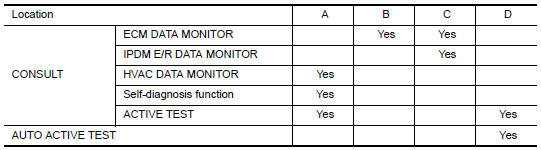
Functional initial inspection chart
Fail-Safe
FAIL-SAFE FUNCTION
- If a communication error exists between the A/C auto amp., the AV control unit and the A/C and AV switch assembly for 30 seconds or longer, air conditioner is controlled under the following conditions:
Compressor: ON
Air outlet: AUTO
Air inlet: FRE (  )
)
Blower fan speed: AUTO
Set temperature: Setting before communication error occurs

 Automatic air conditioner system
System Diagram
CONTROL SYSTEM
The control system consists of input sensors, switches, the A/C auto amp.
(microcomputer) and outputs. The
relationship of these components is as shown in the figure ...
Other materials:
Audio
Some of the information and operations available
on the control panel can also be viewed and
operated on the vehicle information display. The
vehicle information display operations can be
conducted with the switches on the steering
wheel.
Use or
and select
on the vehicle
information disp ...
Air mix door control system
System Diagram
System Description
The air mix doors are automatically controlled so that in-vehicle temperature
is maintained at a predetermined
value by the temperature setting, ambient temperature, intake temperature and
amount of sunload.
SYSTEM OPERATION
The A/C auto amp. receive ...
High-mounted stop lamp
Exploded View
High-mounted stop lamp cover
High-mounted stop lamp bulb
Removal and Installation
REMOVAL
Slide the high-mounted stop lamp rearward on the parcel shelf to
give clearance to the front locking tabs.
Lift the front of the high-mounted stop lamp up and slide it forward ...
Nissan Maxima Owners Manual
- Illustrated table of contents
- Safety-Seats, seat belts and supplemental restraint system
- Instruments and controls
- Pre-driving checks and adjustments
- Monitor, climate, audio, phone and voice recognition systems
- Starting and driving
- In case of emergency
- Appearance and care
- Do-it-yourself
- Maintenance and schedules
- Technical and consumer information
Nissan Maxima Service and Repair Manual

0.0059