Nissan Maxima Service and Repair Manual: Manual function
MANUAL FUNCTION : System Diagram
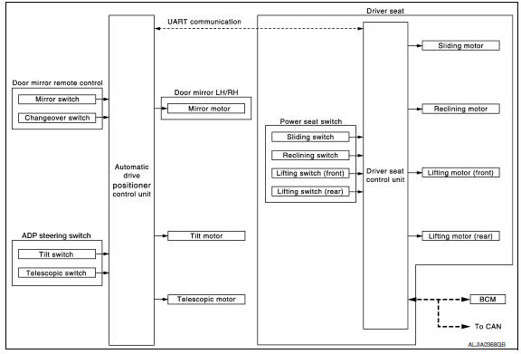
MANUAL FUNCTION : System Descriptio
OUTLINE
The driving position (seat, steering column and door mirror position) can be adjusted manually with power seat switch, ADP steering switch and door mirror remote control switch.
OPERATION PROCEDURE
- Turn ignition switch ON.
- Operate power seat switch, ADP steering switch or door mirror remote control switch.
- The driver seat, steering column or door mirror operates according to the operation of each switch.
DETAIL FLOW
Seat
| Order | Input | Output | Control unit condition |
| 1 | Power seat switch (sliding, lifting, reclining) | - | The power seat switch signal is inputted to the driver seat control unit when the power seat switch is operated. |
| 2 | - | Motors (sliding, lifting, reclining) | The driver seat control unit outputs signals to each motor according to the power seat switch input signal. |
Tilt and Telescopic
| Order | Input | Output | Control unit condition |
| 1 | ADP steering switch | - | The ADP steering switch signal is input to the automatic drive positioner control unit when the ADP steering switch is operated. |
| 2 | - | Motors (tilt, telescopic) | The automatic drive positioner control unit actuates the motors according to the operation of the ADP steering switch signal. |
| 3 | Sensors (tilt, telescopic) | - | The automatic drive positioner control unit recognizes any operation limit of each actuator via each sensor and will not operate the motors anymore at that time. |
Door Mirror
| Order | Input | Output | Control unit condition |
| 1 | Door mirror remote control switch | - | The door mirror remote control switch signal is inputted to the automatic drive positioner control unit when the door mirror remote control switch is operated |
| 2 | - | Motors (Door mirror motor) | The automatic drive positioner control unit actuates each motor according to the operation of the door mirror remote control switch |
NOTE: The door mirrors can be operated manually when ignition switch is in either ACC or ON position. The ignition switch signal (ACC/ON) is transmitted from BCM to the driver seat control unit via CAN communication and from the driver seat control unit to the automatic drive positioner control unit via UART communication.
MANUAL FUNCTION : Component Parts Location

- Push-button ignition switch M38
- BCM M16, M17, M18, M19 (view with instrument panel removed)
- TCM F15
- A. ADP steering switch M39 B. Tilt motor M71, telescopic motor M73
- A. Power seat switch LH B213
B. Reclining motor B222
C. Driver seat control unit B203, B211 - Automatic drive positioner control unit M63, M67 (view with instrument panel removed)
- A. Door mirror LH D4
B. Door mirror RH D107
C. Front door switch LH B8 - Door mirror remote control switch M108
- Seat memory switch D13
: Front
MANUAL FUNCTION : Component Description
CONTROL UNITS
| Item | Function |
| Driver seat control unit |
|
| Automatic drive positioner control unit | Operates the specific motor with the signal from ADP steering switch or door mirror remote control switch |
| BCM |
Recognizes the following status and transmits it to the driver seat control unit via CAN communication.
|
INPUT PARTS
Switches
| Item | Function |
| Power seat switch |
The following switch is installed.
The specific parts can be operated with the operation of each switch. |
| ADP steering switch |
The following switch is installed.
The specific parts can be operated with the operation of each switch. |
| Door mirror remote control switch |
The following switch is installed.
The specific parts can be operated with the operation of each switch. |
Sensors
| Item | Function |
| Tilt and telescopic sensors | Detect the up/down and front/back position of steering column. |
OUTPUT PART
| Item | Function |
| Door mirror motor (LH/RH) | Move the outside mirror face up/down and left/right. |
| Tilt and telescopic motors | Move the steering column up/down and front/back. |
| Lifting motor (front) | Move the seat lifter (front) up/down. |
| Lifting motor (rear) | Move the seat lifter (rear) up/down. |
| Reclining motor | Tilt and raise up the seatback |
| Sliding motor | Slide the seat forward/backward |
 Automatic drive positioner system
AUTOMATIC DRIVE POSITIONER SYSTEM : System Diagram
AUTOMATIC DRIVE POSITIONER SYSTEM : System Description
OUTLINE
The system automatically moves the driver seat, steering column and door
mirr ...
 Memory function
MEMORY FUNCTION : System
MEMORY FUNCTION : System Description
OUTLINE
The driver seat control unit can store the optimum driving positions (seat,
steering column and door mirror position) for ...
Other materials:
Front regulator
Exploded View
Door panel
Door glass
Regulator assembly
Door module assembly
Window motor
Removal and Installation
REMOVAL
Remove the front door finisher. Refer to INT-18, "Removal and
Installation".
Remove the adhesive bolt hole covers.
Reconnect the window switch t ...
System description
ENGINE CONTROL SYSTEM
System Diagram
System Description
ECM performs various controls such as fuel injection control and ignition
timing control.
Component Parts Location
Intake valve timing control solenoid
valve (bank 1)
Electronic controlled engine mount
control solenoid ...
C1147, C1148, C1149, C1150 USV/HSV line
Description
USV1, USV2 (CUT VALVE)
The cut valve shuts off the normal brake fluid path from the master cylinder,
when VDC/TCS is activated.
HSV1, HSV2 (SUCTION VALVE)
The suction valve supplies the brake fluid from the master cylinder to the
pump, when VDC/TCS is activated.
DTC Logic
DTC D ...
Nissan Maxima Owners Manual
- Illustrated table of contents
- Safety-Seats, seat belts and supplemental restraint system
- Instruments and controls
- Pre-driving checks and adjustments
- Monitor, climate, audio, phone and voice recognition systems
- Starting and driving
- In case of emergency
- Appearance and care
- Do-it-yourself
- Maintenance and schedules
- Technical and consumer information
Nissan Maxima Service and Repair Manual

0.0055