Nissan Maxima Service and Repair Manual: Sliding sensor
Description
- The sliding sensor is installed to the seat frame.
- The pulse signal is input to the driver seat control unit when sliding is performed.
- The driver seat control unit counts the pulse and calculates the sliding amount of the seat.
Component Function Check
1. CHECK FUNCTION
- Select "SLIDE PULSE" in "DATA MONITOR" mode with CONSULT.
- Check sliding sensor switch signal under the following conditions.

Diagnosis Procedure
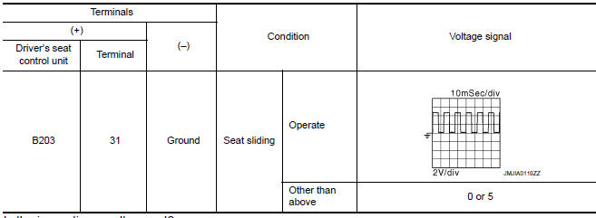
1. CHECK SLIDING SENSOR SIGNAL
- Turn ignition switch ON.
- Read voltage signal between driver seat control unit harness connector and ground with oscilloscope.
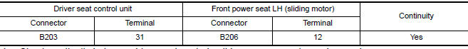
2. CHECK SLIDING SENSOR CIRCUIT
- Turn ignition switch OFF.
- Disconnect driver seat control unit and front power seat LH (sliding motor).
- Check continuity between driver seat control unit harness connector and front power seat LH (sliding motor) harness connector
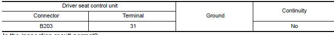
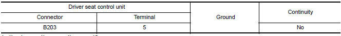
- Check continuity between driver seat control unit harness connector and ground.
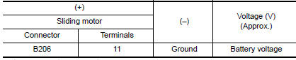
3. CHECK SLIDING SENSOR POWER SUPPLY

- Connect driver seat control unit.
- Turn ignition switch ON.
- Check voltage between front power seat LH (sliding motor) harness connector and ground
4. CHECK SLIDING SENSOR POWER SUPPLY CIRCUIT
- Turn ignition switch OFF.
- Disconnect driver seat control unit.
- Check continuity between driver seat control unit harness connector and front power seat LH (sliding motor) harness connector.

- Check continuity between driver seat control unit harness connector and ground
5. CHECK SLIDING SENSOR GROUND
- Turn ignition switch OFF.
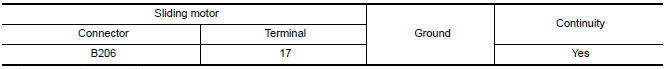
- Check continuity between front power seat LH (sliding motor) harness connector and ground.
 Front door switch (driver side)
Description
Detects front door LH open/close condition.
Component Function Check
1. CHECK FUNCTION
Select "DOOR SW-FL" in "DATA MONITOR" mode with CONSULT.
Check the front door switch signal ...
 Reclining sensor
Description
The reclining motor is installed to the seatback assembly.
The pulse signal is input to the driver seat control unit when the
reclining is operated.
The driver seat control unit ...
Other materials:
Hood
HOOD ASSEMBLY
HOOD ASSEMBLY : Exploded View
Hood hinge cover (LH)
Hood stay (LH)
Hood hinge (LH)
Hood assembly
Hood bumper rubber
Seal
Hood insulator
Hood insulator clips
HOOD ASSEMBLY : Removal and Installation
CAUTION:
Use two people when removing or installi ...
Inspection and adjustment
REAR VIEW MONITOR POSSIBLE ROUTE LINE CENTER POSITION ADJUSTMENT
REAR VIEW MONITOR POSSIBLE ROUTE LINE CENTER POSITION ADJUSTMENT :
Description
Adjust the center position of the possible route line of the rear view
monitor if it is shifted.
REAR VIEW MONITOR POSSIBLE ROUTE LINE CENTER POSITIO ...
Subwoofer
Description
The AV control unit sends audio signals to the BOSE speaker amp. The BOSE
speaker amp. amplifies the
audio signals before sending them to the subwoofers using the audio signal
circuits.
Diagnosis Procedure
1.CONNECTOR CHECK
Check the AV control unit, BOSE speaker amp. and subwo ...
Nissan Maxima Owners Manual
- Illustrated table of contents
- Safety-Seats, seat belts and supplemental restraint system
- Instruments and controls
- Pre-driving checks and adjustments
- Monitor, climate, audio, phone and voice recognition systems
- Starting and driving
- In case of emergency
- Appearance and care
- Do-it-yourself
- Maintenance and schedules
- Technical and consumer information
Nissan Maxima Service and Repair Manual

0.0153