Nissan Maxima Service and Repair Manual: Tilt motor
Description
- The tilt motor is installed to the steering column assembly.
- The tilt motor is activated with the automatic drive positioner control unit.
- The steering column is tilted upward/downward by changing the rotation direction of tilt motor.
Component Function Check
1. CHECK FUNCTION
- Select "TILT MOTOR" in "ACTIVE TEST" mode with CONSULT.
- Check the tilt motor operation.

Diagnosis Procedure
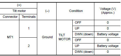
1. CHECK TILT MOTOR POWER SUPPLY

- Turn ignition switch OFF.
- Disconnect tilt motor.
- Turn the ignition switch ON.
- Perform "ACTIVE TEST" ("TILT MOTOR") with CONSULT.
- Check voltage between tilt motor harness connector and ground.
2. CHECK TILT MOTOR CIRCUIT

- Turn ignition switch OFF.
- Disconnect automatic drive positioner control unit.
- Check continuity between automatic drive positioner control unit harness connector and tilt motor harness connecto

- Check continuity between automatic drive positioner control unit harness connector and ground.

 Lifting motor (rear)
Description
The lifting motor (rear) is installed to the seat frame.
The lifting motor (rear) is activated with the driver seat control
unit.
The seat lifter (rear) is moved upward/downward ...
 Telescopic motor
Description
The telescopic motor is installed to the steering column assembly.
The telescopic motor is activated with the automatic drive
positioner control unit.
Compresses the steering co ...
Other materials:
Front tweeter
Removal and Installation
REMOVAL
Remove the front pillar finisher. Refer to INT-24, "Removal and
Installation".
Remove the front tweeter speaker grille. Refer to IP-10, "Exploded
View".
Remove the front tweeter speaker screws (A).
Pull out front tweeter speaker ( ...
Front fog lamp circuit
Description
The IPDM E/R (intelligent power distribution module engine room) controls the
front fog lamp relay based on inputs from the BCM over the CAN communication
lines. When the front fog lamp relay is energized, power flows from the front
fog lamp relay in the IPDM E/R to the front fog ...
U1000 CAN comm circuit
Description
CAN (Controller Area Network) is a serial communication line for real time
application. It is an on-vehicle multiplex
communication line with high data communication speed and excellent error
detection ability. Many electronic
control units are equipped onto a vehicle, and each co ...
Nissan Maxima Owners Manual
- Illustrated table of contents
- Safety-Seats, seat belts and supplemental restraint system
- Instruments and controls
- Pre-driving checks and adjustments
- Monitor, climate, audio, phone and voice recognition systems
- Starting and driving
- In case of emergency
- Appearance and care
- Do-it-yourself
- Maintenance and schedules
- Technical and consumer information
Nissan Maxima Service and Repair Manual

0.0054