Nissan Maxima Service and Repair Manual: B2608 starter relay
Description
Located in IPDM E/R, it runs the starter motor. The starter relay is turned ON by the BCM when the ignition switch is in START position. IPDM E/R transmits the starter relay ON signal to BCM via CAN communication.
DTC Logic
DTC DETECTION LOGIC
NOTE:
-
If DTC B2608 is displayed with DTC U1000, first perform the trouble diagnosis for DTC U1000. Refer to SEC-29, "DTC Logic".
-
If DTC B2608 is displayed with DTC U1010, first perform the trouble diagnosis for DTC U1010. Refer to SEC-30, "DTC Logic".

DTC CONFIRMATION PROCEDURE
1.PERFORM DTC CONFIRMATION PROCEDURE
-
Press the push-button ignition switch under the following conditions.
-
CVT selector lever is in the P or N position.
-
Depress the brake pedal.
-
-
Check "Self diagnostic result" with CONSULT.
Diagnosis Procedure
Regarding Wiring Diagram information, refer to SEC-147, "Wiring Diagram" or SEC-128, "Wiring Diagram".
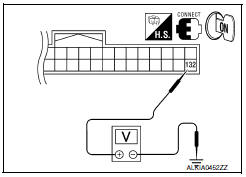
1.CHECK STARTER RELAY
-
Turn ignition switch ON.
-
Check voltage between BCM harness connector and ground under the following condition.

2.CHECK STARTER RELAY CIRCUIT
-
Turn ignition switch OFF.
-
Disconnect BCM harness connector M21 and IPDM E/R harness connector E17.
-
Check continuity between IPDM E/R harness connector E17 (A) terminal 46 and BCM harness connector M21 (B) terminal 132.


4. Check continuity between IPDM E/R harness connector E17 (A) terminal 46 and ground.

3.CHECK INTERMITTENT INCIDENT
Refer to GI-41, "Intermittent Incident".
Inspection End.
 B2605 transmission range switch
Description
BCM confirms the shift position with the following 4
signals.
CVT selector lever
Transmission range switch
P position signal from IPDM E/R (CAN) ...
 B260f engine status
Description
BCM receives the engine status signal from ECM via CAN
communication.
DTC Logic
DTC DETECTION LOGIC
NOTE:
If DTC B260F is displayed with DTC
U1000, first perform the troubl ...
Other materials:
U122A AV control unit
DTC Logic
Diagnosis Procedure
1.PERFORM THE SELF-DIAGNOSIS
When U122A is detected, write configuration data with "MULTI AV" of CONSULT.
U122E AV CONTROL UNIT
DTC Logic
DTC DETECTION LOGIC
...
P0705 transmission range switch A
Description
The Transmission range switch is included in the control valve
assembly.
The Transmission range switch includes 4 transmission position
switches.
TCM judges the selector lever position by the Transmission range
switch signal.
DTC Logic
DTC DETECTI ...
Wiring diagram
ELECTRONICALLY CONTROLLED POWER STEERING SYSTEM
Wiring Diagram
...
Nissan Maxima Owners Manual
- Illustrated table of contents
- Safety-Seats, seat belts and supplemental restraint system
- Instruments and controls
- Pre-driving checks and adjustments
- Monitor, climate, audio, phone and voice recognition systems
- Starting and driving
- In case of emergency
- Appearance and care
- Do-it-yourself
- Maintenance and schedules
- Technical and consumer information
Nissan Maxima Service and Repair Manual

0.0056