Nissan Maxima Service and Repair Manual: Power window system
System Diagram

System Description
MAIN POWER WINDOW AND DOOR LOCK/UNLOCK SWITCH
INPUT/OUTPUT SIGNAL CHART
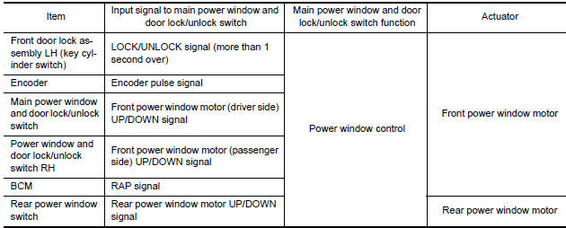
POWER WINDOW AND DOOR LOCK/UNLOCK SWITCH RH
NPUT/OUTPUT SIGNAL CHART

POWER WINDOW OPERATION
- Power window system is operable during the retained power operation timer after turning ignition switch ON and OFF.
- Main power window and door lock/unlock switch can open/close all windows.
- Front & rear power window switch can open/close the corresponding windows.
POWER WINDOW AUTO-OPERATION (FRONT DRIVER SIDE & PASSENGER SIDE)
- AUTO UP/DOWN operation can be performed when main power window and door lock/unlock switch & power window and door lock/unlock switch RH turns to AUTO.
- Encoder continues detecting the movement of power window motor and transmits to power window switch as the encoder pulse signal while power window motor is operating.
- Power window switch reads the changes of encoder signal and stops AUTO operation when door glass is at fully opened/closed position.
- Power window motor is operable in case encoder is malfunctioning.
RETAINED POWER OPERATION
- Retained power operation is an additional power supply function
that enables power window system to operate
during the 45 seconds even when ignition switch is turned OFF.
Retained power function cancel conditions
- Front door CLOSE (door switch OFF)→OPEN (door switch ON).
- When ignition switch is ON.
- When timer time passes. (45 seconds)
POWER WINDOW LOCK
Ground circuit inside main power window and door lock/unlock switch shuts off when power window lock switch is ON. This inhibits power window switch operation except with the main power window and door lock/ unlock switch.
ANTI-PINCH OPERATION (FRONT DRIVER SIDE & PASSENGER SIDE)
- Pinch foreign material in the door glass during AUTO-UP operation, and it is the anti-pinch function that lowers the door glass 150 mm (5.91 in) or 2 seconds when detected.
- Encoder continues detecting the movement of power window motor and transmits to power window switch as the encoder pulse signal while power window motor is operating.
- Resistance is applied to the power window motor rotation that changes the frequency of encoder pulse signal if foreign material is trapped in the door glass.
- Power window switch controls to lower the window glass for 150 mm or 2 seconds after it detects encoder pulse signal frequency change.
OPERATION CONDITION
- When all door glass AUTO-UP operation is performed (anti-pinch function does not operate just before the door glass closes and is fully closed).
NOTE: Depending on environment and driving conditions, if a similar impact or load is applied to the door glass, it may lower.
KEY CYLINDER SWITCH OPERATION
Hold the door key cylinder to the LOCK or UNLOCK direction for 1 second or more to OPEN or CLOSE front power windows when ignition switch is OFF. In addition, it stops when key position is moved to NEUTRAL when operating.
OPERATION CONDITION
- Ignition switch OFF.
- Hold door key cylinder to LOCK position for 1 second or more to perform CLOSE operation of the door glass.
- Hold door key cylinder to UNLOCK position for 1 second or more to perform OPEN operation of the door glass.
KEYLESS POWER WINDOW DOWN OPERATION (FRONT DRIVER SIDE & PASSENGER SIDE)
All power windows open when the unlock button on Intelligent Key is activated and kept pressed for more than 3 secondsNOTE with the ignition switch OFF. The windows keep opening if the unlock button is continuously pressed.
The power window opening stops when the following operations are performed:
- When the unlock button is kept pressed more than 15 seconds.
- When the ignition switch is turned ON while the power window opening is operated.
- When the unlock button is released.
While retained power operation is active, keyless power window down function cannot be operated.
Keyless power window down operation mode can be changed by "PW DOWN SET" mode in "WORK SUPPORT".
Refer to BCS-24, "INTELLIGENT KEY : CONSULT Function (BCM - INTELLIGENT KEY)".
NOTE: Use CONSULT to change settings.
MODE 1 (3 sec) / MODE 2 (OFF) / MODE 3 (5 sec)
Component Parts Location

- BCM M16, M17, M18 (view with combination meter removed)
- Front power window motor LH D9 Front power window motor RH D104
- Rear power window motor LH D204 Rear power window motor RH D304
- Main power window and door lock/ unlock switch D7, D8
- Power window and door lock/unlock switch RH D105
- Rear power window switch LH D203 Rear power window switch RH D303
- Front door lock assembly LH (key cylinder switch) D10
- Front door switch LH B8 Front door switch RH B108
Component Description


 Diagnosis system (BCM)
COMMON ITEM
COMMON ITEM : CONSULT Function (BCM - COMMON ITEM)
APPLICATION ITEM
CONSULT performs the following functions via CAN communication with BCM.
SYSTEM APPLICATION
BCM can perform the ...
Other materials:
Environmental factors influence the rate of corrosion
Moisture
Accumulation of sand, dirt and water on the vehicle
body underside can accelerate corrosion.
Wet floor coverings will not dry completely inside
the vehicle and should be removed for drying to
avoid floor panel corrosion.
Relative humidity
Corrosion will be accelerated in areas of h ...
RGB (B: blue) signal circuit
Description
Transmit the image displayed with AV control unit with RGB signal to the
display unit.
Diagnosis Procedure
1.CHECK CONTINUITY RGB (B: BLUE) SIGNAL CIRCUIT
Turn ignition switch OFF.
Disconnect display unit connector M141 and AV control unit
connector
M154.
Check con ...
Bose speaker amp
Removal and Installation
Bose speaker amp.
Bose speaker amp. screws
REMOVAL
NOTE: If removing the BOSE speaker amp.
bracket, it is necessary to remove the parcel shelf finisher. The BOSE
speaker amp. can be removed without removing the BOSE speaker amp. bracket.
Disconnect the ...
Nissan Maxima Owners Manual
- Illustrated table of contents
- Safety-Seats, seat belts and supplemental restraint system
- Instruments and controls
- Pre-driving checks and adjustments
- Monitor, climate, audio, phone and voice recognition systems
- Starting and driving
- In case of emergency
- Appearance and care
- Do-it-yourself
- Maintenance and schedules
- Technical and consumer information
Nissan Maxima Service and Repair Manual

0.0074