Nissan Maxima Service and Repair Manual: BCM (body control module)
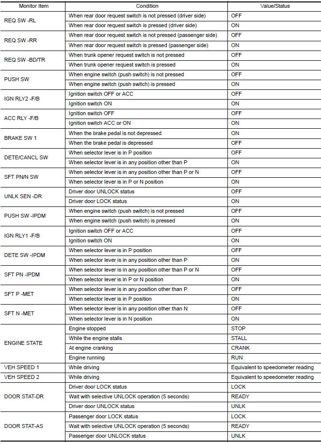
Reference Value
NOTE: The Signal Tech II Tool (J-50190) can be used to perform the following functions. Refer to the Signal Tech II User Guide for additional information.
- Activate and display TPMS transmitter IDs
- Display tire pressure reported by the TPMS transmitter
- Read TPMS DTCs
- Register TPMS transmitter IDs
- Check Intelligent Key relative signal strength
- Confirm vehicle Intelligent Key antenna signal strength
VALUES ON THE DIAGNOSIS TOOL


Terminal Layout

Physical Values


Fail Safe


DTC Inspection Priority Chart
If some DTCs are displayed at the same time, perform inspections one by one based on the following priority chart.


DTC Index
NOTE: Details of time display
- CRNT: Displays when there is a malfunction now or after returning to the normal condition until turning ignition switch OFF → ON again.
- - 1 - 39: Displayed if any previous malfunction is present when current condition is normal. It increases 1 → 2 → 3...38 → 39 after returning to the normal condition whenever ignition switch OFF → ON. The counter remains at 39 even if the number of cycles exceeds it. It is counted from 1 again when turning ignition switch OFF → ON after returning to the normal condition if the malfunction is detected again.


 Sunroof motor assembly
Reference Value
TERMINAL LAYOUT
PHYSICAL VALUES
...
Other materials:
On board diagnostic (OBD) system
Trouble Diagnosis Introduction
CAUTION:
Do not use electrical test equipment on any circuit related to
the SRS unless instructed to do so inthis Service Manual. SRS wiring
harnesses can be identified by yellow and/or orange harness connectors.
Do not attempt to repair, splice or modify ...
Air conditioning cut control
System Diagram
System Description
INPUT/OUTPUT SIGNAL CHART
*1: This signal is sent to the ECM via the CAN communication line.
*2: ECM determines the start signal status by the signals of engine speed and
battery voltage.
SYSTEM DESCRIPTION
This system improves engine operation when ...
Magnet clutch
Description
SYSTEM DESCRIPTION
A/C auto amp. controls A/C compressor operation by ambient temperature and
signal from ECM.
Low Temperature Protection Control
A/C auto amp. will turn the A/C compressor ON or OFF as determined
by a signal detected by ambient sensor.
When ambient temper ...
Nissan Maxima Owners Manual
- Illustrated table of contents
- Safety-Seats, seat belts and supplemental restraint system
- Instruments and controls
- Pre-driving checks and adjustments
- Monitor, climate, audio, phone and voice recognition systems
- Starting and driving
- In case of emergency
- Appearance and care
- Do-it-yourself
- Maintenance and schedules
- Technical and consumer information
Nissan Maxima Service and Repair Manual

0.0129