Nissan Maxima Service and Repair Manual: Turn signal lamp circuit
Description
The BCM monitors inputs from the combination switch to determine when to activate the turn signals. The BCM outputs voltage direction to the left and right turn signals during turn signal operation or both during hazard warning operation. The BCM sends a turn signal indicator request to the combination meter via the CAN communication lines.
The BCM performs the fast flasher operation (fail-safe) if any bulb or harness of the turn signal lamp circuit is open.
NOTE: Turn signal lamp blinks at normal speed when using the hazard warning lamp.
Component Function Check
1.CHECK TURN SIGNAL LAMP
CONSULT
- Select "FLASHER" of BCM (FLASHER) active test item.
- While operating the test item, check that the turn signal lamp blinks.
LH : Turn signal lamp LH blinking
RH : Turn signal lamp RH blinking
OFF : The turn signal lamp
Diagnosis Procedure
1.CHECK TURN SIGNAL LAMP BULB
Check the applicable lamp bulb to be sure the proper bulb standard is in use and the bulb is not open.
2.CHECK TURN SIGNAL LAMP OUTPUT VOLTAGE
- Turn the ignition switch OFF.
- Disconnect front combination lamp connector, door mirror connector (if equipped with turn signal in mirror) and rear combination lamp connector.
- Turn the ignition switch ON.
- With turn signal switch operating, check the voltage between the front combination lamp harness connector and ground.
- With turn signal switch operating, check the voltage between the rear combination lamp harness connector and ground.
- With turn signal switch operating, check the voltage between the door mirror (if equipped with turn signals in the mirrors) harness connector and ground.


3.CHECK TURN SIGNAL LAMP CIRCUIT FOR OPEN
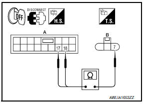


- Turn ignition switch OFF.
- Disconnect BCM connector M17.
- Check continuity between the BCM harness connector (A) and the front combination lamp connector (B).
- Check continuity between the BCM harness connector (A) and the rear combination lamp harness connector (B).
- Check continuity between the BCM harness connector (A) and the door mirror connector (B) (if equipped with turn signal in mirror).


4.CHECK TURN SIGNAL LAMP SHORT CIRCUIT

Check continuity between the BCM harness connector and ground

5.CHECK TURN SIGNAL LAMP GROUND CIRCUIT


- Turn ignition switch OFF.
- Check continuity between the front combination lamp and ground.
- Check continuity between the rear combination lamp and ground.
- Check continuity between the door mirror and ground (if equipped with turn signal in mirror).


 Parking lamp circuit
Description
The IPDM E/R (intelligent power distribution module engine room) controls the
tail lamp relay based on inputs from the BCM over the CAN communication
lines. When the tail lamp relay i ...
 Optical sensor
Description
The optical sensor converts the outside brightness (lux) to voltage and
transmits the optical sensor signal to the BCM.
Component Function Check
1.CHECK OPTICAL SENSOR SIG ...
Other materials:
NISSAN Vehicle Immobilizer System keys
You can only drive your vehicle using the Intelligent
Keys which are registered to the NISSAN
Vehicle Immobilizer System components in your
vehicle.
The mechanical key can be used for all the locks.
Never leave the keys in the vehicle.
Additional or replacement keys:
If you still have a key ...
Front drive shaft
Removal and Installation (LH)
Drive shaft
Cotter pin
REMOVAL
Remove wheel and tire using power tool. Refer to WT-60, "Adjustment".
Remove wheel sensor from steering knuckle. Refer to BRC-102,
"Removal and Installation - Front Wheel Sensor".CAUTION: Do not
pull o ...
Main line between ADP and DLC circuit
Diagnosis Procedure
1.CHECK CONNECTOR
Turn the ignition switch OFF.
Disconnect the battery cable from the negative terminal.
Check the following terminals and connectors for damage, bend and
loose connection (connector side
and harness side).
Harness connector B1
Harness connect ...
Nissan Maxima Owners Manual
- Illustrated table of contents
- Safety-Seats, seat belts and supplemental restraint system
- Instruments and controls
- Pre-driving checks and adjustments
- Monitor, climate, audio, phone and voice recognition systems
- Starting and driving
- In case of emergency
- Appearance and care
- Do-it-yourself
- Maintenance and schedules
- Technical and consumer information
Nissan Maxima Service and Repair Manual

0.0059