Nissan Maxima Service and Repair Manual: ECU diagnosis information
BCM (BODY CONTROL MODULE)
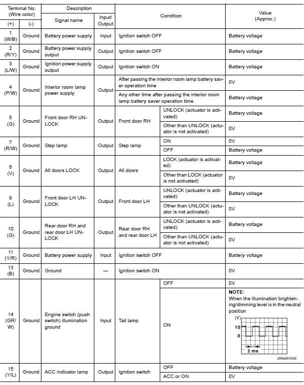
Reference Value
NOTE: The Signal Tech II Tool (J-50190) can be used to perform the following functions. Refer to the Signal Tech II User Guide for additional information.
- Activate and display TPMS transmitter IDs
- Display tire pressure reported by the TPMS transmitter
- Read TPMS DTCs
- Register TPMS transmitter IDs
- Check Intelligent Key relative signal strength
- Confirm vehicle Intelligent Key antenna signal strength
VALUES ON THE DIAGNOSIS TOOL


Terminal Layout

Physical Values


Fail Safe


DTC Inspection Priority Chart
If some DTCs are displayed at the same time, perform inspections one by one based on the following priority chart.


DTC Index
NOTE: Details of time display
- CRNT: Displays when there is a malfunction now or after returning to the normal condition until turning ignition switch OFF → ON again.
- 1 - 39: Displayed if any previous malfunction is present when current condition is normal. It increases 1 → 2 → 3...38 → 39 after returning to the normal condition whenever ignition switch OFF → ON. The counter remains at 39 even if the number of cycles exceeds it. It is counted from 1 again when turning ignition switch OFF → ON after returning to the normal condition if the malfunction is detected again.


 Combination switch output circuit
Diagnosis Procedure
1. CHECK OUTPUT 1 - 5 SYSTEM CIRCUIT FOR OPEN
Turn the ignition switch OFF.
Disconnect the BCM and combination switch.
Check continuity between BCM harness connector and c ...
 Wiring diagram
BCM (BODY CONTROL MODULE)
Wiring Diagram
...
Other materials:
Condenser
CONDENSER
CONDENSER : Removal and Installation
REMOVAL
Discharge the refrigerant. Refer to HA-28, "Recycle Refrigerant".
Remove the RH hoodledge cover.
Remove the front bumper fascia. Refer to EXT-16, "Removal and
Installation".
Disconnect the high-pressure pipe from the condenser pip ...
The oil pressure warning lamp does not turn on
Description
The oil pressure warning lamp stays off when the ignition
switch is turned ON.
Diagnosis Procedure
1.CHECK OIL PRESSURE WARNING LAMP
Perform IPDM E/R auto active test. Refer to PCS-11,
"Diagnosis Description".
2.CHECK OIL PRESSURE SWITCH SIGNAL CIRCUIT
Check the oil pressure sw ...
Clearing the programmed information
The following procedure clears the programmed
information from both buttons. Individual buttons
cannot be cleared. However, individual buttons
can be reprogrammed. For additional information,
refer to "Reprogramming a single
HomeLink button" in this section.
To clear all programming:
1. Press ...
Nissan Maxima Owners Manual
- Illustrated table of contents
- Safety-Seats, seat belts and supplemental restraint system
- Instruments and controls
- Pre-driving checks and adjustments
- Monitor, climate, audio, phone and voice recognition systems
- Starting and driving
- In case of emergency
- Appearance and care
- Do-it-yourself
- Maintenance and schedules
- Technical and consumer information
Nissan Maxima Service and Repair Manual

0.006