Nissan Maxima Service and Repair Manual: DTC/circuit diagnosis
POWER SUPPLY AND GROUND CIRCUIT
COMBINATION METER
COMBINATION METER : Diagnosis Procedure
Regarding Wiring Diagram information, refer to MWI-87, "Wiring Diagram".
1.CHECK FUSES
Check for blown combination meter fuses.

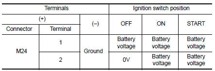
2.POWER SUPPLY CIRCUIT CHECK
- Disconnect combination meter connector.
- Check voltage between combination meter harness connector M24 terminals 1, 2, and ground.

3.GROUND CIRCUIT CHECK
- Turn ignition switch OFF.
- Check continuity between combination meter harness connector terminals 3, 4, 23 and ground.


BCM (BODY CONTROL MODULE)
BCM (BODY CONTROL MODULE) : Diagnosis Procedure
Regarding Wiring Diagram information, refer to BCS-67, "Wiring Diagram".
1. CHECK FUSE AND FUSIBLE LINK
Check if the following BCM fuses or fusible link are blown.

2. CHECK POWER SUPPLY CIRCUIT
- Turn ignition switch OFF.
- Disconnect BCM.
- Check voltage between BCM harness connector and ground.

3. CHECK GROUND CIRCUIT
Check continuity between BCM harness connector and ground.

 Diagnosis system (BCM)
BUZZER
BUZZER : CONSULT Function (BCM - BUZZER)
DATA MONITOR
ACTIVE TEST
...
 Meter buzzer circuit
Description
The buzzer for warning chime system is installed in the
combination meter.
The combination meter sounds the alarm buzzer based on the signals
transmitted from various units.
...
Other materials:
Rear disc brake
Disassembly and Assembly
Union bolt
Brake hose
Copper sealing washer
Cap
Bleed valve
Lower sliding pin bolt
Upper sliding pin bolt
Bushing
Cylinder body
Piston seal
Piston
Piston boot
Retaining ring
Sliding pin boot
Torque member bolt
Washer
Torque m ...
Automatic drive positioner control unit
Reference Value
TERMINAL LAYOUT
PHYSICAL VALUES
...
Key slot illumination
Description
Blinks when Intelligent Key insertion is required.
Component Function Check
1. CHECK FUNCTION
With CONSULT
Check key slot illumination KEY SLOT ILLUMI in Active Test mode.
Diagnosis Procedure
1. CHECK KEY SLOT ILLUMINATION OUTPUT SIGNAL
Check voltage between key slot connector ...
Nissan Maxima Owners Manual
- Illustrated table of contents
- Safety-Seats, seat belts and supplemental restraint system
- Instruments and controls
- Pre-driving checks and adjustments
- Monitor, climate, audio, phone and voice recognition systems
- Starting and driving
- In case of emergency
- Appearance and care
- Do-it-yourself
- Maintenance and schedules
- Technical and consumer information
Nissan Maxima Service and Repair Manual

0.013