Nissan Maxima Service and Repair Manual: Composite image signal circuit
Description
AV control unit transmits the playback DVD image signal and AUX image signal to the display unit.
Diagnosis Procedure
1.CHECK CONTINUITY COMPOSITE IMAGE SIGNAL CIRCUIT

- Turn ignition switch OFF.
- Disconnect AV control unit connector M163 and display unit connector M142.
- Check continuity between AV control unit connector M163 (A) terminal 40 and display unit connector M142 (B) terminal 18.
- Check continuity between AV control unit connector M163 (A) terminal 40 and ground.


2.CHECK AUX COMPOSITE SIGNAL
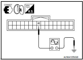
- Connect AV control unit connector M163 and display unit connector M142.
- Turn ignition switch ON.
- Check signal between AV control unit harness connector M163 terminal 40 and ground.

 RGB digital image signal circuit
Description
Transmit the image displayed with AV control unit with RGB digital image
signal to the display unit.
Diagnosis Procedure
1.CHECK CONTINUITY RGB DIGITAL IMAGE SIGNAL CIRCUIT
Tu ...
 Aux image signal circuit
Description
Transmits the image signal of AUX device from auxiliary input jacks to
AV control unit.
AV control unit transmits the image signal that is input to the
display unit.
Diagnos ...
Other materials:
B2636, B2637, B2638, B2639, B2654, B2655 mode door motor
Description
COMPONENT DESCRIPTION
Mode Door Motor
The mode door motor (1) is attached to the heater & cooling unit
assembly.
It rotates so that air is discharged from the outlet set by the
A/C
auto amp. Motor rotation is conveyed to a link which activates the
mode door
DT ...
Intelligent key system/engine start function symptoms
Symptom Table
Engine cannot be started with all Intelligent Keys.
CAUTION:
Follow Trouble Diagnosis Flowchart
referring to "SEC-4, "Work Flow"". Determine malfunctioning
condition before performing this diagnosis.
Check that vehicle is under the
condition shown in "Conditio ...
On board diagnostic (OBD) system
Trouble Diagnosis Introduction
CAUTION:
Do not use electrical test equipment on any circuit related to
the SRS unless instructed to do so inthis Service Manual. SRS wiring
harnesses can be identified by yellow and/or orange harness connectors.
Do not attempt to repair, splice or modify ...
Nissan Maxima Owners Manual
- Illustrated table of contents
- Safety-Seats, seat belts and supplemental restraint system
- Instruments and controls
- Pre-driving checks and adjustments
- Monitor, climate, audio, phone and voice recognition systems
- Starting and driving
- In case of emergency
- Appearance and care
- Do-it-yourself
- Maintenance and schedules
- Technical and consumer information
Nissan Maxima Service and Repair Manual

0.0062