Nissan Maxima Service and Repair Manual: Hydraulic control system
System Diagram

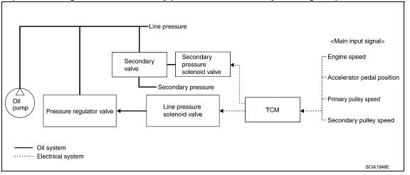
System Description
The hydraulic control mechanism consists of the oil pump directly driven by the engine, the hydraulic control valve that controls line pressure and transmission, and the input signal lin
LINE PRESSURE AND SECONDARY PRESSURE CONTROL
- When an input torque signal equivalent to the engine driving force is transmitted from the ECM to the TCM, the TCM controls the line pressure solenoid valve and secondary pressure solenoid valve.
- Line pressure solenoid valve activates pressure regulator valve, and line pressure from oil pump is adjusted for the optimum driving condition. Secondary pressure is controlled by lowering line pressure.
Normal Control
Optimize the line pressure and secondary pressure, depending on driving conditions, on the basis of the throttle position, the engine speed, the primary pulley (input) revolution speed, the secondary pulley (output) revolution speed, the brake signal, the transmission range switch signal, the lock-up signal, the voltage, the target gear ratio, the fluid temperature, and the fluid pressure.
Feedback Control
For the normal fluid control and the select fluid control, secondary pressure is detected for feedback control by using a secondary pressure sensor to set a high-precision secondary pressure.
Component Parts Location

- CVT shift selector assembly (Manual mode select switch and manual mode position select switch)
- Secondary speed sensor
- CVT unit harness connector
- TCM
- Accelerator pedal position (APP) sensor
- Stop lamp switch
- Shift positioner indicator Manual mode indicator DS mode indicator
- Paddle shifters
Component Description
TRANSAXLE ASSEMBLY

EXCEPT TRANSAXLE ASSEMBLY

 Mechanical system
Cross-Sectional View
Converter housing
Oil pump
Forward clutch
Reverse brake
Planetary carrier
Primary pulley
Steel belt
Sun ge ...
 Control system
System Diagram
System Description
The CVT senses vehicle operating conditions through various sensors. It
always controls the optimum shift
position and reduces shifting and lock-up shocks.
T ...
Other materials:
System temporarily unavailable
When radar blockage is detected, the system will
be deactivated automatically. The "Side Radar
Obstruction" warning message will appear and
the BSW/RCTA indicator (white) will blink A in
the vehicle information display.
The system is not available until the conditions no
longer exist.
...
Power seat for driver side
Wiring Diagram - Without Automatic Drive Positioner
...
Precaution
PRECAUTIONS
Precaution for Supplemental Restraint System (SRS) "AIR BAG" and "SEAT
BELT
PRE-TENSIONER"
The Supplemental Restraint System such as "AIR BAG" and "SEAT BELT
PRE-TENSIONER", used along
with a front seat belt, helps to reduce the risk or severity of injury to ...
Nissan Maxima Owners Manual
- Illustrated table of contents
- Safety-Seats, seat belts and supplemental restraint system
- Instruments and controls
- Pre-driving checks and adjustments
- Monitor, climate, audio, phone and voice recognition systems
- Starting and driving
- In case of emergency
- Appearance and care
- Do-it-yourself
- Maintenance and schedules
- Technical and consumer information
Nissan Maxima Service and Repair Manual

0.0054