Nissan Maxima Service and Repair Manual: Engine speed signal circuit
Description
ECM sends engine speed signal to power steering control unit.
Diagnosis Procedure
1.PERFORM ECM SELF-DIAGNOSIS
With CONSULT
Perform ECM self-diagnosis.
2.CHECK HARNESS BETWEEN ECM AND POWER STEERING CONTROL UNIT FOR OPEN

- Turn the ignition switch OFF.
- Disconnect ECM connector E10.
- Disconnect power steering control unit connector.
- Check continuity between ECM connector E10 (A) terminal 94
and power steering control unit connector M59 (B) terminal 10.

3.CHECK HARNESS BETWEEN ECM AND POWER STEERING CONTROL UNIT FOR SHORT


- Check continuity between ECM connector E10 terminal 94 and
ground. - Turn ignition switch ON.
- Check voltage between ECM connector E10 terminal 94 and
ground.


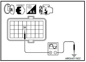
4.CHECK ENGINE SPEED SIGNAL (ECM SIDE)
- Turn the ignition switch OFF.
- Connect ECM connector E10.
- Start the engine.
- Check signal between ECM connector E10 terminal 94 and
ground with oscilloscope.

5.CHECK ENGINE SPEED SIGNAL (POWER STEERING CONTROL UNIT SIDE)

- Turn the ignition switch OFF.
- Connect power steering control unit harness connector.
- Start the engine.
- Check signal between power steering control unit harness connector
M59 terminal 10 and ground with oscilloscope

6.CHECK TERMINALS AND HARNESS CONNECTORS
- Check power steering control unit pin terminals for damage or loose connection with harness connector.
- Check ECM pin terminals for damage or loose connection with harness connector.
 Power steering solenoid valve
Description
Power steering solenoid valve controls the power steering oil pressure in the
gear housing assembly.
Diagnosis Procedure
1.CHECK POWER STEERING SOLENOID VALVE SIGNAL
Start eng ...
 Vehicle speed signal circuit
Description
Combination meter sends vehicle speed signal to power steering control unit.
Diagnosis Procedure
1.PERFORM COMBINATION METER SELF-DIAGNOSIS
Perform combination meter self-diagnosis.
2 ...
Other materials:
In-vehicle sensor
Removal and Installation
REMOVAL
Remove the instrument lower panel LH. Refer to IP-19, "Removal and
Installation".
Remove the in-vehicle sensor screw and the in-vehicle sensor.
INSTALLATION
Installation is in the reverse order of removal.
CAUTION:
Make sure that the asp ...
B263D, B263E, B263f intake door motor
Description
COMPONENT DESCRIPTION
Intake Door Motor
The intake door motor (1) is attached to the blower unit.
It rotates so that air is drawn from inlets set by the A/C auto
amp.
Motor rotation is conveyed to a lever which activates the intake
door.
DTC Logic
DTC DETECTION L ...
NISSAN vehicle immobilizer system
The NISSAN Vehicle Immobilizer System will not
allow the engine to start without the use of a
registered key.
If the engine fails to start using a registered key
(for example, when interference is caused by
another registered key, an automated toll road
device or automatic payment device on ...
Nissan Maxima Owners Manual
- Illustrated table of contents
- Safety-Seats, seat belts and supplemental restraint system
- Instruments and controls
- Pre-driving checks and adjustments
- Monitor, climate, audio, phone and voice recognition systems
- Starting and driving
- In case of emergency
- Appearance and care
- Do-it-yourself
- Maintenance and schedules
- Technical and consumer information
Nissan Maxima Service and Repair Manual

0.0058