Nissan Maxima Service and Repair Manual: Seat cushion thermal electric device
Description
Provides cooling and heat for the seat cushion.
Component Function Check
1.CHECK SEAT CUSHION THERMAL ELECTRIC DEVICE FUNCTION
- Turn the climate controlled seat switch to the H (Heat) HI position and check that the seat cushion thermal electric device operates correctly.
- Turn the climate controlled seat switch to the C (Cool) HI position and check that the seat cushion thermal electric device operates correctly.
Diagnosis Procedure
Regarding Wiring Diagram information, refer to SE-44, "Wiring Diagram".
1.CHECK SEAT CUSHION THERMAL ELECTRIC DEVICE
Perform thermal electric device component inspection for the seat cushion. Refer to SE-16, "Component Inspection (Thermal Electric Device)".
2.CHECK SEAT CUSHION THERMAL ELECTRIC DEVICE CIRCUITS
- Turn ignition switch OFF.
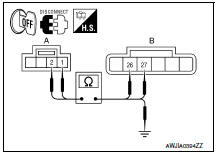
- Disconnect seat cushion thermal electric device connector and climate controlled seat control unit connector B217.
- Check continuity between seat cushion thermal electric device connector B219 (A) terminals 1, 2 and climate controlled seat control unit connector B217 (B) terminals 26, 27.

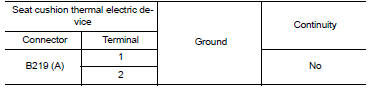
4. Check continuity between seat cushion thermal electric device connector B219 (A) terminals 1, 2 and ground.
3.CHECK SEAT CUSHION THERMAL ELECTRIC DEVICE SENSOR CIRCUITS
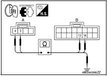
- Disconnect climate controlled seat control unit connector B212.
- Check continuity between seat cushion thermal electric device connector B219 (A) terminals 3, 4 and climate controlled seat control unit connector B212 (B) terminals 13, 14.

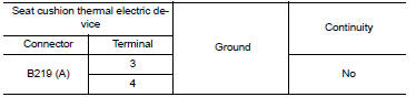
3. Check continuity between seat cushion thermal electric device connector B219 (A) terminals 3, 4 and ground.
Component Inspection (Thermal Electric Device)
1.CHECK THERMAL ELECTRIC DEVICE
- Turn ignition switch OFF.
- Disconnect thermal electric device connector.
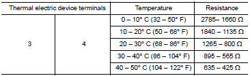
- Measure the resistance of the thermal electric device between terminals 1 and 2.
NOTE:
The resistance value in the table below will change under any of the following conditions:
- air blowing across the thermal electric device
- changing the surrounding temperature of the thermal electric device
- measuring at other than 23C (73F)

2.CHECK THERMAL ELECTRIC DEVICE SENSOR
Measure the resistance of the thermal electric device sensor between terminals 3 and 4.
 Climate controlled seat blower motor
Description
Sends airflow to the seat cushion and seatback.
Component Function Check
1.CHECK CLIMATE CONTROLLED SEAT BLOWER MOTOR FUNCTION
Turn the climate controlled seat switch to the H (Heat) L ...
 Seatback thermal electric device
Description
Provides cooling and heat for the seatback.
Component Function Check
1.CHECK SEATBACK THERMAL ELECTRIC DEVICE FUNCTION
Turn the climate controlled seat switch to the H (Heat) HI
...
Other materials:
Diagnosis system (BCM)
COMMON ITEM
CONSULT Function (BCM - COMMON ITEM)
APPLICATION ITEM
CONSULT performs the following functions via CAN communication with BCM.
SYSTEM APPLICATION
BCM can perform the following functions.
RETAINED PWR
CONSULT Function (BCM - RETAINED PWR)
DATA MONITOR
...
Microphone
Removal and Installation
REMOVAL
Remove the front room/map lamp assembly. Refer to INL-84, "Removal
and Installation".
Detach the microphone connector (A).
Remove the front room/map lamp covers (1), then remove the
map lamp assembly cover (2).
Release the m ...
Tel antenna
Removal and Instalation
REMOVAL
Disconnect the battery negative terminal. Refer to PG-67, "Removal
and Installation (Battery)".
Remove the rear parcel shelf finisher. Refer to INT-28, "Removal
and Installation".
Remove the Bluetooth antenna screw (A).
Detach the Bluetooth anten ...
Nissan Maxima Owners Manual
- Illustrated table of contents
- Safety-Seats, seat belts and supplemental restraint system
- Instruments and controls
- Pre-driving checks and adjustments
- Monitor, climate, audio, phone and voice recognition systems
- Starting and driving
- In case of emergency
- Appearance and care
- Do-it-yourself
- Maintenance and schedules
- Technical and consumer information
Nissan Maxima Service and Repair Manual

0.0143