Nissan Maxima Service and Repair Manual: Sliding sensor
Description
- The sliding sensor is installed to the seat frame.
- The pulse signal is input to the driver seat control unit when sliding is performed.
- The driver seat control unit counts the pulse and calculates the sliding amount of the seat.
Component Function Check
1. CHECK FUNCTION
- Select "SLIDE PULSE" in "DATA MONITOR" mode with CONSULT.
- Check sliding sensor switch signal under the following conditions.

Diagnosis Procedure
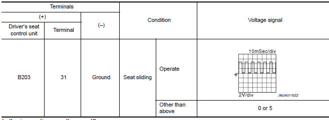
1. CHECK SLIDING SENSOR SIGNAL
- Turn ignition switch ON.
- Read voltage signal between driver seat control unit harness connector and ground with oscilloscope.
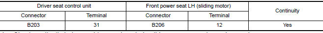
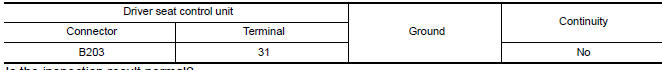
2. CHECK SLIDING SENSOR CIRCUIT
- Turn ignition switch OFF.
- Disconnect driver seat control unit and front power seat LH (sliding motor).
- Check continuity between driver seat control unit harness connector and front power seat LH (sliding motor) harness connector
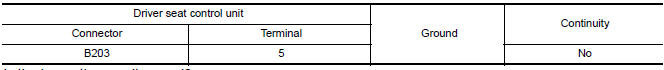
- Check continuity between driver seat control unit harness connector and ground.
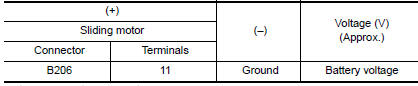
3. CHECK SLIDING SENSOR POWER SUPPLY

- Connect driver seat control unit.
- Turn ignition switch ON.
- Check voltage between front power seat LH (sliding motor) harness connector and ground
4. CHECK SLIDING SENSOR POWER SUPPLY CIRCUIT
- Turn ignition switch OFF.
- Disconnect driver seat control unit.
- Check continuity between driver seat control unit harness connector and front power seat LH (sliding motor) harness connector.

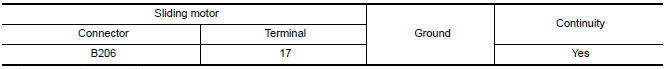
- Check continuity between driver seat control unit harness connector and ground
5. CHECK SLIDING SENSOR GROUND
- Turn ignition switch OFF.
- Check continuity between front power seat LH (sliding motor) harness connector and ground.
 Front door switch (driver side)
Description
Detects front door LH open/close condition.
Component Function Check
1. CHECK FUNCTION
Select "DOOR SW-FL" in "DATA MONITOR" mode with CONSULT.
Check the front door switch signal ...
 Reclining sensor
Description
The reclining motor is installed to the seatback assembly.
The pulse signal is input to the driver seat control unit when the
reclining is operated.
The driver seat control unit ...
Other materials:
P0453 evap control system pressure sensor
Description
The EVAP control system pressure sensor detects pressure in the
purge line. The sensor output voltage to the ECM increases as pressure
increases.
DTC Logic
DTC DETECTION LOGIC
DTC CONFIRMATION PROCEDURE
1.PRECONDITIONING
If DTC Confirmation Procedure has been previously ...
Front lower link
Removal and Installation
Removal
Remove the front lower link nut and bolt from the rear axle
housing using power tools.
Remove the adjusting bolt and nut from the rear suspension
member using power tools.
Remove the front lower link.
Installation
Installation is in the reverse o ...
Entry/exit function
This system is designed so that the driver's seat
and automatic operation steering column will automatically
move when the shift lever is in the P
(Park) position. This allows the driver to get into
and out of the driver's seat more easily.
The driver's seat will slide backward and the
steer ...
Nissan Maxima Owners Manual
- Illustrated table of contents
- Safety-Seats, seat belts and supplemental restraint system
- Instruments and controls
- Pre-driving checks and adjustments
- Monitor, climate, audio, phone and voice recognition systems
- Starting and driving
- In case of emergency
- Appearance and care
- Do-it-yourself
- Maintenance and schedules
- Technical and consumer information
Nissan Maxima Service and Repair Manual

0.0088