Nissan Maxima Service and Repair Manual: B2556 push-button ignition switch
Description
The switch that changes the power supply position. BCM maintains the power supply position status. BCM changes the power supply position with the operation of the push-button ignition switch.
DTC Logic
DTC DETECTION LOGIC

DTC CONFIRMATION PROCEDURE
1.PERFORM DTC CONFIRMATION PROCEDURE
-
Start the engine and wait for at least 100 seconds.
-
Check "Self Diagnostic Result" with CONSULT.
Diagnosis Procedure
Regarding Wiring Diagram information, refer to SEC-147, "Wiring Diagram" or SEC-128, "Wiring Diagram".
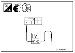
1.CHECK PUSH-BUTTON IGNITION SWITCH INPUT SIGNAL
-
Turn ignition switch OFF.
-
Disconnect push-button ignition switch harness connector.
-
Check voltage between push-button ignition switch harness connector M38 terminal 4 and ground.

2.CHECK PUSH-BUTTON IGNITION SWITCH
Refer to SEC-47, "Component Inspection".
3.CHECK INTERMITTENT INCIDENT
Refer to GI-41, "Intermittent Incident".
Inspection End.
4.CHECK PUSH-BUTTON IGNITION SWITCH CIRCUIT FOR SHORT
-
Disconnect BCM harness connector and IPDM E/R harness connector.
-
Check continuity between push-button ignition switch harness connector M38 terminal 4 and ground.


Component Inspection
1.CHECK PUSH-BUTTON IGNITION SWITCH
-
Turn ignition switch OFF.
-
Disconnect push-button ignition switch harness connector.
-
Check continuity between push-button ignition switch terminals under the following conditions.


 B2555 stop lamp
Description
BCM detects the stop lamp status and confirms the stop
lamp switch ON/OFF status. BCM confirms the
engine start condition according to the stop lamp switch ON/OFF status.
DTC Logic
...
 B2557 vehicle speed
Description
BCM receives the 2 vehicle speed signals via CAN
communication. One signal is transmitted by the "combination
meter". Another signal is transmitted by "ABS actuator and electric unit ...
Other materials:
Child safety rear door lock
Child safety locks help prevent the rear doors
from being opened accidentally, especially when
small children are in the vehicle.
The child safety lock levers are located on the
edge of the rear doors.
When the lever is in the unlock position 2 , the
door can be opened from the outside ...
Wiring diagram
POWER WINDOW SYSTEM
Wiring Diagram
...
Heating (A/C OFF)
The air conditioner does not activate. When you
need to heat only, use this mode.
1. Press the AUTO button.
2. Turn the temperature control dial to set the
desired temperature.
The temperature of the passenger compartment
will be maintained automatically. Air
flow distribution and fa ...
Nissan Maxima Owners Manual
- Illustrated table of contents
- Safety-Seats, seat belts and supplemental restraint system
- Instruments and controls
- Pre-driving checks and adjustments
- Monitor, climate, audio, phone and voice recognition systems
- Starting and driving
- In case of emergency
- Appearance and care
- Do-it-yourself
- Maintenance and schedules
- Technical and consumer information
Nissan Maxima Service and Repair Manual

0.0059