Nissan Maxima Service and Repair Manual: ECU diagnosis information
BCM (BODY CONTROL MODULE)
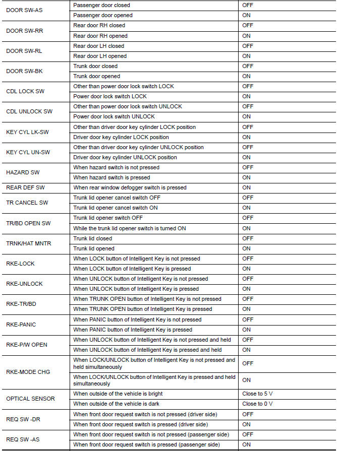
Reference Value
NOTE: The Signal Tech II Tool (J-50190) can be used to perform the following functions. Refer to the Signal Tech II User Guide for additional information.
- Activate and display TPMS transmitter IDs
- Display tire pressure reported by the TPMS transmitter
- Read TPMS DTCs
- Register TPMS transmitter IDs
- Check Intelligent Key relative signal strength
- Confirm vehicle Intelligent Key antenna signal strength
VALUES ON THE DIAGNOSIS TOOL


Terminal Layout

Physical Values


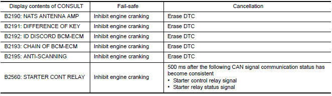
Fail Safe

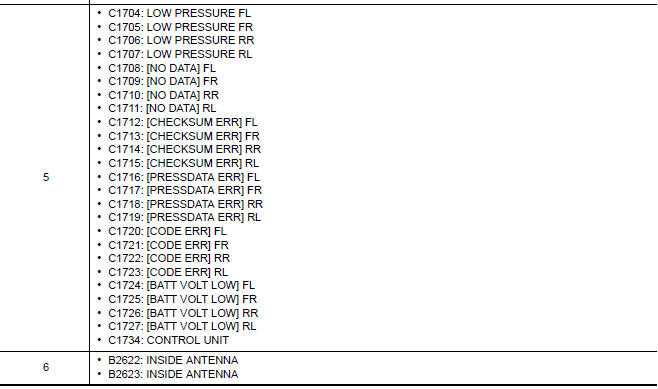
DTC Inspection Priority Chart
If some DTCs are displayed at the same time, perform inspections one by one based on the following priority chart.

DTC Index
NOTE: Details of time display
- CRNT: Displays when there is a malfunction now or after returning to the normal condition until turning ignition switch OFF → ON again.
- 1 - 39: Displayed if any previous malfunction is present when current condition is normal. It increases 1 → 2 → 3...38 → 39 after returning to the normal condition whenever ignition switch OFF → ON. The counter remains at 39 even if the number of cycles exceeds it. It is counted from 1 again when turning ignition switch OFF → ON after returning to the normal condition if the malfunction is detected again


 Push-button ignition switch illumination circuit
Description
Provides the power supply and the ground to control the push-button ignition
switch illumination.
Component Function Check
1.CHECK PUSH-BUTTON IGNITION SWITCH ILLUMINATION OPERATION
...
 Wiring diagram
...
Other materials:
Precaution
PRECAUTIONS
Precaution for Supplemental Restraint System (SRS) "AIR BAG" and "SEAT BELT
PRE-TENSIONER"
with a front seat belt, helps to reduce the risk or severity of injury to the
driver and front passenger for certain
types of collision. This system includes seat belt switch inputs and dua ...
Tilt &telescopic switch ground circuit
Diagnosis Procedure
1. CHECK ADP STEERING SWITCH (TILT & TELESCOPIC SWITCH) GROUND CIRCUIT
Turn ignition switch OFF.
Disconnect ADP steering switch (tilt & telescopic switch).
Check continuity between ADP steering switch (tilt & telescopic
switch) and ground.
...
Seat belt buckle switch signal circuit
Description
Transmits a seat belt buckle switch LH signal to the combination meter.
Component Function Check
1. CHECK COMBINATION METER INPUT SIGNAL
Start engine.
Monitor seat belt warning lamp while fastening and unfastening the
driver seat belt.
Diagnosis Procedure
Regarding Wiring ...
Nissan Maxima Owners Manual
- Illustrated table of contents
- Safety-Seats, seat belts and supplemental restraint system
- Instruments and controls
- Pre-driving checks and adjustments
- Monitor, climate, audio, phone and voice recognition systems
- Starting and driving
- In case of emergency
- Appearance and care
- Do-it-yourself
- Maintenance and schedules
- Technical and consumer information
Nissan Maxima Service and Repair Manual

0.0054