Nissan Maxima Service and Repair Manual: Trouble diagnosis
Condition of Error Detection
DTC (e.g. U1000 and U1001) of CAN communication is indicated on SELF-DIAG RESULTS on CONSULT if a CAN communication signal is not transmitted or received between units for 2 seconds or more.
CAN COMMUNICATION SYSTEM ERROR
- CAN communication line open (CAN-H, CAN-L, or both)
- CAN communication line short (ground, between CAN communication lines, other harnesses)
- Error of CAN communication control circuit of the unit connected to CAN communication line WHEN DTC OF CAN COMMUNICATION IS INDICATED EVEN THOUGH CAN COMMUNICATION SYSTEM IS NORMAL
- Removal/installation of parts: Error may be detected when removing and installing CAN communication unit and related parts while turning the ignition switch ON. (A DTC except for CAN communication may be detected.)
- Fuse blown out (removed): CAN communication of the unit may cease.
- Voltage drop: Error may be detected if voltage drops due to discharged battery when turning the ignition switch ON (Depending on the control unit which carries out CAN communication).
- Error may be detected if the power supply circuit of the control unit, which carries out CAN communication, malfunctions (Depending on the control unit which carries out CAN communication).
- Error may be detected if reprogramming is not completed normally.
CAUTION:
CAN communication system is normal if DTC of CAN communication is indicated on SELF-DIAG RESULTS of CONSULT under the above conditions. Erase the memory of the self-diagnosis of each unit.
Symptom When Error Occurs in CAN Communication System
In CAN communication system, multiple units mutually transmit and receive signals. Each unit cannot transmit and receive signals if any error occurs on CAN communication line. Under this condition, multiple control units related to the root cause malfunction or go into fail-safe mode.
ERROR EXAMPLE
NOTE:
- Each vehicle differs in symptom of each unit under fail-safe mode and CAN communication line wiring.
- Refer to LAN-20, "Abbreviation List" for the unit abbreviation.
Example: TCM branch line open circuit


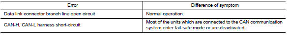
Example: Data link connector branch line open circuit


NOTE:
- When data link connector branch line is open, transmission and reception of CAN communication signals are not affected. Therefore, no symptoms occur. However, be sure to repair malfunctioning circuit.
- The model (all units on CAN communication system are Diag on CAN) cannot perform CAN diagnosis with CONSULT if the following error occurs. The error is judged by the symptom.
Example: Main Line Between Data Link Connector and ABS Actuator and Electric Unit (Control Unit) Open Circuit


Example: CAN-H, CAN-L Harness Short Circuit


CAN Diagnosis with CONSULT
CAN diagnosis on CONSULT extracts the root cause by receiving the following information.
- Response to the system call
- Control unit diagnosis information
- Self-diagnosis
- CAN diagnostic support monitor
Self-Diagnosis
If communication signals cannot be transmitted or received among units communicating via CAN communication line, CAN communication-related DTC is displayed on the CONSULT "Self Diagnostic Result" screen.
NOTE:
The following table shows examples of CAN communication-related DTC. For other DTC, refer to the applicable sections.

CAN Diagnostic Support Monitor
MONITOR ITEM (CONSULT)
Example: CAN DIAG SUPPORT MNTR indication

Without PAST

With PAST

MONITOR ITEM (ON-BOARD DIAGNOSIS)
NOTE:
For some models, CAN communication diagnosis result is received from the vehicle monitor.
Example: Vehicle Display

How to Use CAN Communication Signal Chart
The CAN communication signal chart lists the signals needed for trouble diagnosis. It is useful for detecting the root cause by finding a signal related to the symptom, and by checking transmission and reception unit.

 Diag on can
Description
"Diag on CAN" is a diagnosis using CAN communication instead of previous DDL1
and DDL2 communication
lines, between control units and diagnosis unit.
System Diagram
...
 Basic inspection
DIAGNOSIS AND REPAIR WORKFLOW
Trouble Diagnosis Flow Chart
Trouble Diagnosis Procedure
INTERVIEW WITH CUSTOMER
Interview with the customer is important to detect the root cause of CAN
communi ...
Other materials:
Rear door speaker
Removal and Installation
REMOVAL
Remove the rear door finisher. Refer to INT-21, "Removal and
Installation".
Remove the rear door speaker screws (A).
Disconnect the harness connector (B) from the rear door speaker
(1) and remove.
INSTALLATION
Installation is in the reverse order ...
Environmental factors influence the rate of corrosion
Moisture
Accumulation of sand, dirt and water on the vehicle
body underside can accelerate corrosion.
Wet floor coverings will not dry completely inside
the vehicle and should be removed for drying to
avoid floor panel corrosion.
Relative humidity
Corrosion will be accelerated in areas of h ...
M&A branch line circuit
Diagnosis Procedure
1.CHECK CONNECTOR
Turn the ignition switch OFF.
Disconnect the battery cable from the negative terminal.
Check the terminals and connectors of the combination meter for
damage, bend and loose connection
(unit side and connector side).
2.CHECK HARNESS FOR OPEN CI ...
Nissan Maxima Owners Manual
- Illustrated table of contents
- Safety-Seats, seat belts and supplemental restraint system
- Instruments and controls
- Pre-driving checks and adjustments
- Monitor, climate, audio, phone and voice recognition systems
- Starting and driving
- In case of emergency
- Appearance and care
- Do-it-yourself
- Maintenance and schedules
- Technical and consumer information
Nissan Maxima Service and Repair Manual

0.0136