Nissan Maxima Service and Repair Manual: DTC/circuit diagnosis
POWER SUPPLY AND GROUND CIRCUIT
COMBINATION METER
COMBINATION METER : Diagnosis Procedure
Regarding Wiring Diagram information, refer to MWI-87, "Wiring Diagram".
1.CHECK FUSES
Check for blown combination meter fuses.

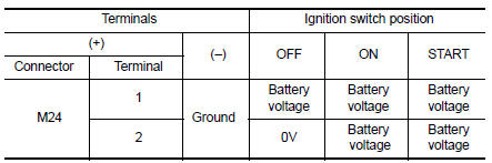
2.POWER SUPPLY CIRCUIT CHECK
- Disconnect combination meter connector.
- Check voltage between combination meter harness connector M24 terminals 1, 2, and ground.

3.GROUND CIRCUIT CHECK
- Turn ignition switch OFF.
- Check continuity between combination meter harness connector terminals 3, 4, 23 and ground.


BCM (BODY CONTROL MODULE)
BCM (BODY CONTROL MODULE) : Diagnosis Procedure
Regarding Wiring Diagram information, refer to BCS-67, "Wiring Diagram".
1. CHECK FUSE AND FUSIBLE LINK
Check if the following BCM fuses or fusible link are blown.

2. CHECK POWER SUPPLY CIRCUIT
- Turn ignition switch OFF.
- Disconnect BCM.
- Check voltage between BCM harness connector and ground.

3. CHECK GROUND CIRCUIT
Check continuity between BCM harness connector and ground.

 Diagnosis system (BCM)
BUZZER
BUZZER : CONSULT Function (BCM - BUZZER)
DATA MONITOR
ACTIVE TEST
...
 Meter buzzer circuit
Description
The buzzer for warning chime system is installed in the
combination meter.
The combination meter sounds the alarm buzzer based on the signals
transmitted from various units.
...
Other materials:
Diagnosis and repair workflow
Work Flow
OVERALL SEQUENCE
DETAILED FLOW
1. GET INFORMATION FOR SYMPTOM
Get the detailed information from the customer about the symptom (the
condition and the environment when the incident/malfunction occurred).
2. CHECK DTC
Check DTC.
Perform the following procedure if DTC is displa ...
Service data and specifications (SDS)
Wheel Bearing
Drive Shaft
*: Boot installation grooves
Dynamic Damper
NOTE: Measured from wheel side
Boot Bands
...
Recommended fluids and lubricants
FOR USA AND CANADA
FOR USA AND CANADA : Fluids and Lubricants
*1: For further details, see "Engine Oil Recommendation".
*2: NISSAN recommends Genuine NISSAN Ester Oil available at a NISSAN dealer.
*3: Use only Genuine NISSAN CVT Fluid NS-2. Using transmission fluid other than
Genuine NIS ...
Nissan Maxima Owners Manual
- Illustrated table of contents
- Safety-Seats, seat belts and supplemental restraint system
- Instruments and controls
- Pre-driving checks and adjustments
- Monitor, climate, audio, phone and voice recognition systems
- Starting and driving
- In case of emergency
- Appearance and care
- Do-it-yourself
- Maintenance and schedules
- Technical and consumer information
Nissan Maxima Service and Repair Manual

0.0068