Nissan Maxima Service and Repair Manual: Brake master cylinder
Exploded View
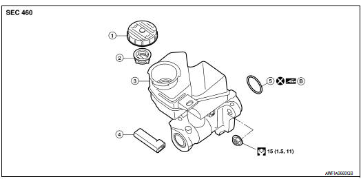
- Reservoir cap
- Oil strainer (blue)
- Master cylinder assembly
- Brake fluid level switch harness connector
- O-ring
- PBC (Poly Butyl Cuprysil) grease or silicone-based grease
Removal and Installation
CAUTION:
- Do not to splash brake fluid on painted areas; it may cause paint damage. If brake fluid is splashed on painted areas, wash it away with water immediately.
- Refill with new brake fluid.
- Do not reuse drained brake fluid.
NOTE: When removing components such as hoses, tubes/lines, etc., cap or plug openings to prevent fluid from spilling.
REMOVAL
- Remove the engine room cover. Refer to EM-23, "Removal and Installation".
- Remove the air cleaner and air duct. Refer to EM-24, "Removal and Installation".
- Disconnect the harness connector from the brake fluid level switch.
- Disconnect master cylinder brake tubes, using a suitable tool.
- Remove master cylinder nuts.
- Remove master cylinder assembly and O-ring.
CAUTION: Do not reuse O-ring.
INSTALLATION
Installation is in the reverse order of removal.

- Apply silicone grease to brake booster at position (A) as shown, be
sure the O-ring is in proper position when installing master cylinder
to brake booster.
CAUTION: Do not reuse O-ring. - Tighten brake tube flare nut to the specified torque using a suitable tool. Refer to BR-20, "Hydraulic Circuit".
- Refill the brake hydraulic system with new brake fluid and bleed air. Refer to BR-16, "Bleeding Brake System".
- If necessary, adjust the brake booster input rod length. Refer to BR-46, "Brake Booster".
 Brake tube and hose
Hydraulic Circuit
Actuator
Master cylinder
Brake booster
Connector A. Union bolt
18.2 N*m (1.9 kg-m, 13 ft-lb)
B. Flare nut M12
22.1 N*m (2.3 kg-m, 16 ft-lb)
C. Flare nut M ...
 Brake booster
Exploded View
Master cylinder assembly
Brake booster
Brake pedal
Lock nut
Gasket
Removal and installation
NOTE:
When removing components such as hoses, tubes/lines, etc., cap ...
Other materials:
P0340, P0345 CMP sensor (PHASE)
Description
The camshaft position sensor (PHASE) senses the retraction of
camshaft (INT) to identify a particular cylinder. The camshaft position
sensor (PHASE) senses the piston position.
When the crankshaft position sensor (POS) system becomes inoperative,
the camshaft position senso ...
Front fog lamp
Exploded View
Front bumper fascia
Front fog lamp
Front fog lamp bracket
Clip
Spring nuts
Removal and Installation
FRONT FOG LAMP
Removal
Remove the front bumper fascia. Refer to EXT-16, "Removal and
Installation".
Disconnect the harness connector from the fog lamp.
R ...
Slip indicator lamp
Description
Component Function Check
1.CHECK SLIP INDICATOR LAMP OPERATION
Check that the lamp illuminates for approximately 2 seconds after the
ignition switch is turned ON.
Diagnosis Procedure
1.CHECK SELF-DIAGNOSIS
Perform ABS actuator and electric unit (control unit) self-diagnosis
...
Nissan Maxima Owners Manual
- Illustrated table of contents
- Safety-Seats, seat belts and supplemental restraint system
- Instruments and controls
- Pre-driving checks and adjustments
- Monitor, climate, audio, phone and voice recognition systems
- Starting and driving
- In case of emergency
- Appearance and care
- Do-it-yourself
- Maintenance and schedules
- Technical and consumer information
Nissan Maxima Service and Repair Manual

0.0063