Nissan Maxima Service and Repair Manual: Steering column
Without Electric Motor

- -4. Steering column assembly nut tightening order
- Steering wheel
- Combination switch and spiral cable
- Steering column assembly
- Hole cover seal
- Herbie clip
- Hole cover
- Lower shaft assembly
With Electric Motor

- -4. Steering column assembly nut tightening order
- Steering wheel
- Combination switch and spiral cable
- Steering column assembly
- Hole cover seal
- Herbie clip
- Hole cover
- Lower shaft assembly
Removal and Installation
REMOVAL
Hole Cover Seal, Hole Cover and Lower Shaft Assembly
- Set wheels to the straight-ahead position.
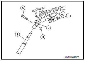
- Remove lower side bolt (A) of lower shaft assembly (1).
- Steering gear (2)

- Remove the instrument lower panel LH.

- Remove bolt (A) and nut (B) of column upper joint (2), then remove lower shaft assembly (1). CAUTION: Do not reuse column upper joint nut.
- Loosen herbie clip, then remove hole cover seal from hole cover.
- Remove nuts of hole cover, and then remove clamp and hole cover from dash panel.
Steering Column Assembly

- Set wheels to the straight-ahead position.
- Remove instrument side finisher (LH). Refer to IP-10, "Exploded View".
- Remove instrument lower panel LH. Refer to IP-19, "Removal and Installation".
- Remove lower knee protector (LH) bolts (
 )(, then remove lower knee protector (LH)
(1). Refer to IP-10, "Exploded View".
)(, then remove lower knee protector (LH)
(1). Refer to IP-10, "Exploded View". - Remove steering column upper and lower covers. Refer to IP- 10, "Exploded View".
- Remove combination switch and spiral cable. Refer to SR-15, "Removal and Installation".
- Disconnect each switch harness connector installed to steering column assembly, and then disconnect harness clips from steering column assembly.
- Remove bolt (A) and nut (B) of column upper joint (2).
- Lower shaft assembly (1)
CAUTION: Do not reuse column upper joint nut.
- Remove steering column assembly nuts, then remove steering column assembly.
INSPECTION AFTER REMOVAL
Hole Cover Seal, Hole Cover and Lower Shaft Assembly Check each part of hole cover seal, hole cover and steering column and lower shaft assembly for damage or other malfunctions. Replace if necessary.
Steering Column Assembly
- Check each part of steering column assembly for damage or other malfunctions. Replace entire steering column assembly if any parts are damaged.
- Measure the length (L) as shown if vehicle has been involved in a minor collision. Replace steering column assembly if outside the specifications.

- Measure steering column rotating torque using Tool. Replace steering column assembly if outside the standard.
Tool number : ST3127S000 (J-25765-A)
- Check tilt and telescopic mechanism operating range (L1), (L2) as shown.
INSTALLATION
Hole Cover Seal, Hole Cover and Lower Shaft Assembly
Installation is in the reverse order of removal.
- When installing lower shaft assembly to steering gear assembly, follow the procedure listed below.
- Set rack of steering gear in the neutral position. NOTE: To get the neutral position of rack, turn gear sub-assembly and measure the distance of inner socket, and then measure the intermediate position of the distance.
- Align rear cover cap projection (A) with the marking position (B) of gear housing assembly.
- Install slit part of lower shaft assembly (C) aligning with the projection (A) of rear cover cap (1). Make sure that the slit part of lower shaft assembly (C) is aligned with both the projection (A) of rear cover cap (1) and the marking position (B) of gear housing assembly.

Steering Column Assembly
Installation is in the reverse order of removal.
 Telescopic motor
Exploded View
Steering column assembly
Telescope motor
Telescope motor link bracket
Tilt motor
Tilt motor bolt cap
Removal and Installation
REMOVAL
Remove instrument lower pan ...
 Steering gear and linkage
Exploded View
Cotter pin
Steering gear assembly Front
Removal and Installation
NOTE: When removing components such as
hoses, tubes/lines, etc., cap or plug openings to prevent fluid ...
Other materials:
Extended storage switch
The extended storage switch is used when the
vehicle is in transit from the factory. It is located in
the fuse panel to the left of the steering wheel on
the instrument panel. If any electrical equipment
does not operate, ensure the extended storage
switch is pushed fully in place, as shown ...
Rear stabilizer
Removal and Installation
Removal
Remove each rear stabilizer connecting rod nut using power tools.
Disconnect the rear stabilizer from each rear stabilizer
connecting rod.
Remove each rear stabilizer clamp bolt using power tools.
Remove the rear stabilizer.
If necessary, remove each ...
Additional service when replacing transaxle assembly
Description
When replacing the transaxle assembly, perform the following work.
ERASING, LOADING AND STORING OF CALIBRATION DATA
The TCM acquires calibration data (individual characteristic
value) of each solenoid that is stored in the
ROM assembly (in the control valve). This enabl ...
Nissan Maxima Owners Manual
- Illustrated table of contents
- Safety-Seats, seat belts and supplemental restraint system
- Instruments and controls
- Pre-driving checks and adjustments
- Monitor, climate, audio, phone and voice recognition systems
- Starting and driving
- In case of emergency
- Appearance and care
- Do-it-yourself
- Maintenance and schedules
- Technical and consumer information
Nissan Maxima Service and Repair Manual

0.0069