Nissan Maxima Service and Repair Manual: Engine speed signal circuit
Description
ECM sends engine speed signal to power steering control unit.
Diagnosis Procedure
1.PERFORM ECM SELF-DIAGNOSIS
With CONSULT
Perform ECM self-diagnosis.
2.CHECK HARNESS BETWEEN ECM AND POWER STEERING CONTROL UNIT FOR OPEN

- Turn the ignition switch OFF.
- Disconnect ECM connector E10.
- Disconnect power steering control unit connector.
- Check continuity between ECM connector E10 (A) terminal 94
and power steering control unit connector M59 (B) terminal 10.

3.CHECK HARNESS BETWEEN ECM AND POWER STEERING CONTROL UNIT FOR SHORT


- Check continuity between ECM connector E10 terminal 94 and
ground. - Turn ignition switch ON.
- Check voltage between ECM connector E10 terminal 94 and
ground.


4.CHECK ENGINE SPEED SIGNAL (ECM SIDE)
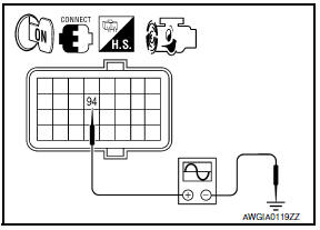
- Turn the ignition switch OFF.
- Connect ECM connector E10.
- Start the engine.
- Check signal between ECM connector E10 terminal 94 and
ground with oscilloscope.

5.CHECK ENGINE SPEED SIGNAL (POWER STEERING CONTROL UNIT SIDE)

- Turn the ignition switch OFF.
- Connect power steering control unit harness connector.
- Start the engine.
- Check signal between power steering control unit harness connector
M59 terminal 10 and ground with oscilloscope

6.CHECK TERMINALS AND HARNESS CONNECTORS
- Check power steering control unit pin terminals for damage or loose connection with harness connector.
- Check ECM pin terminals for damage or loose connection with harness connector.
 Power steering solenoid valve
Description
Power steering solenoid valve controls the power steering oil pressure in the
gear housing assembly.
Diagnosis Procedure
1.CHECK POWER STEERING SOLENOID VALVE SIGNAL
Start eng ...
 Vehicle speed signal circuit
Description
Combination meter sends vehicle speed signal to power steering control unit.
Diagnosis Procedure
1.PERFORM COMBINATION METER SELF-DIAGNOSIS
Perform combination meter self-diagnosis.
2 ...
Other materials:
Battery saver output/power supply circuit
Description
Provides the interior room lamp power supply. Also cuts the power supply when
the interior room lamp battery saver is activated.
Component Function Check
1.CHECK BATTERY SAVER OUTPUT/POWER SUPPLY FUNCTION
CONSULT
Turn ignition switch ON.
Turn each interior room lamp ON.
...
Front disc brake
Disassembly and Assembly
Union bolt
Copper sealing washer
Brake hose
Cap
Bleed valve
Sliding pin bolt
Piston seal
Piston
Piston boot
Cylinder body
Upper sliding pin
Lower sliding pin bolt
Torque member bolt
Washer
Sliding pin boot
Bushing
Torque memb ...
System description
HEATED STEERING WHEEL
System Diagram
System Description
The heated steering wheel switch controls the heated steering relay. When the
switch is turned on, the relay is energized and the heated steering system
will operate. The heated steering system will turn off when the steering
wheel ...
Nissan Maxima Owners Manual
- Illustrated table of contents
- Safety-Seats, seat belts and supplemental restraint system
- Instruments and controls
- Pre-driving checks and adjustments
- Monitor, climate, audio, phone and voice recognition systems
- Starting and driving
- In case of emergency
- Appearance and care
- Do-it-yourself
- Maintenance and schedules
- Technical and consumer information
Nissan Maxima Service and Repair Manual

0.0078