Nissan Maxima Service and Repair Manual: Tilt motor
Description
- The tilt motor is installed to the steering column assembly.
- The tilt motor is activated with the automatic drive positioner control unit.
- The steering column is tilted upward/downward by changing the rotation direction of tilt motor.
Component Function Check
1. CHECK FUNCTION
- Select "TILT MOTOR" in "ACTIVE TEST" mode with CONSULT.
- Check the tilt motor operation.

Diagnosis Procedure
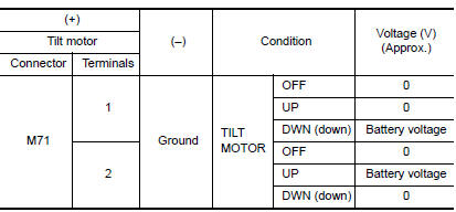
1. CHECK TILT MOTOR POWER SUPPLY

- Turn ignition switch OFF.
- Disconnect tilt motor.
- Turn the ignition switch ON.
- Perform "ACTIVE TEST" ("TILT MOTOR") with CONSULT.
- Check voltage between tilt motor harness connector and ground.
2. CHECK TILT MOTOR CIRCUIT

- Turn ignition switch OFF.
- Disconnect automatic drive positioner control unit.
- Check continuity between automatic drive positioner control unit harness connector and tilt motor harness connecto

- Check continuity between automatic drive positioner control unit harness connector and ground.

 Lifting motor (rear)
Description
The lifting motor (rear) is installed to the seat frame.
The lifting motor (rear) is activated with the driver seat control
unit.
The seat lifter (rear) is moved upward/downward ...
 Telescopic motor
Description
The telescopic motor is installed to the steering column assembly.
The telescopic motor is activated with the automatic drive
positioner control unit.
Compresses the steering co ...
Other materials:
Vehicle speed signal circuit
Description
Combination meter sends vehicle speed signal to power steering control unit.
Diagnosis Procedure
1.PERFORM COMBINATION METER SELF-DIAGNOSIS
Perform combination meter self-diagnosis.
2.CHECK HARNESS BETWEEN COMBINATION METER AND POWER STEERING CONTROL UNIT FOR
OPEN
Turn the ...
Power supply and ground circuit
Diagnosis Procedure
1. CHECK FUSES AND FUSIBLE LINK
Check that the following IPDM E/R fuses or fusible link are not blown.
2. CHECK POWER SUPPLY CIRCUIT
Turn ignition switch OFF.
Disconnect IPDM E/R connectors.
Check voltage between IPDM E/R harness connector and ground.
3. CHE ...
P0605 ECM
Description
The ECM consists of a microcomputer and connectors for signal
input and output and for power supply. The ECM controls the engine
DTC Logic
DTC DETECTION LOGIC
DTC CONFIRMATION PROCEDURE
1.PRECONDITIONING
If DTC Confirmation Procedure has been previously conducted, always ...
Nissan Maxima Owners Manual
- Illustrated table of contents
- Safety-Seats, seat belts and supplemental restraint system
- Instruments and controls
- Pre-driving checks and adjustments
- Monitor, climate, audio, phone and voice recognition systems
- Starting and driving
- In case of emergency
- Appearance and care
- Do-it-yourself
- Maintenance and schedules
- Technical and consumer information
Nissan Maxima Service and Repair Manual

0.0076