Nissan Maxima Service and Repair Manual: BCM (body control module)
Reference Value
NOTE:
The Signal Tech II Tool (J-50190) can be used to perform the following functions. Refer to the Signal Tech II User Guide for additional information.
-
Activate and display TPMS transmitter IDs
-
Display tire pressure reported by the TPMS transmitter
-
Read TPMS DTCs
-
Register TPMS transmitter IDs
-
Check Intelligent Key relative signal strength
-
Confirm vehicle Intelligent Key antenna signal strength
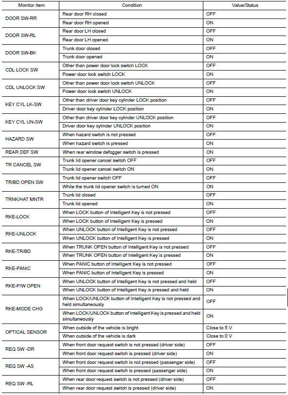
VALUES ON THE DIAGNOSIS TOOL


Terminal Layout

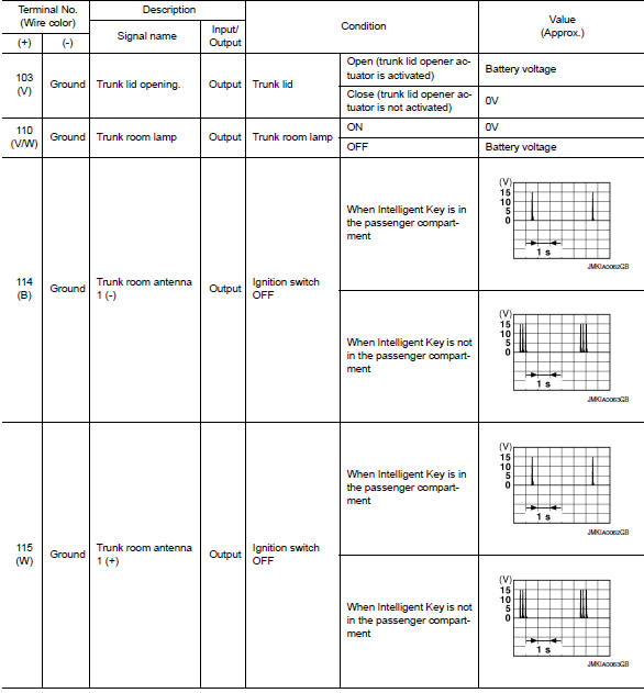
Physical Values


Fail Safe


DTC Inspection Priority Chart
If some DTCs are displayed at the same time, perform inspections one by one based on the following priority chart.


DTC Index
NOTE:
Details of time display
-
CRNT: Displays when there is a malfunction now or after returning to the normal condition until turning ignition switch OFF → ON again.
-
1 - 39: Displayed if any previous malfunction is present when current condition is normal. It increases 1 → 2 → 3...38 → 39 after returning to the normal condition whenever ignition switch OFF → ON. The counter remains at 39 even if the number of cycles exceeds it. It is counted from 1 again when turning ignition switch OFF → ON after returning to the normal condition if the malfunction is detected again.


 Combination meter
Reference Value
VALUES ON THE DIAGNOSIS TOOL
NOTE:
* The monitor will indicate "OFF" even though
the brake warning lamp is on if either of the following conditions exist:
The parking ...
 IPDM E/R (intelligent power distribution module engine room)
Reference Value
VALUES ON THE DIAGNOSIS TOOL
TERMINAL LAYOUT
Fail Safe
CAN COMMUNICATION CONTROL
When CAN communication with ECM and BCM is impossible, IPDM E/R performs
fail-s ...
Other materials:
AV branch line circuit
Diagnosis Procedure
1.CHECK CONNECTOR
Turn the ignition switch OFF.
Disconnect the battery cable from the negative terminal.
Check the terminals and connectors of the AV control unit for
damage, bend and loose connection (unit
side and connector side).
2.CHECK HARNESS FOR OPEN CIRC ...
Periodic maintenance
FRONT SUSPENSION ASSEMBLY
Inspection and Adjustment
INSPECTION
Make sure the mounting conditions (looseness, backlash) of each component and
component conditions (wear, damage) are normal.
LOWER BALL JOINT END PLAY
Set front wheels in a straight-ahead position. Do not depress
brake peda ...
C1111 pump motor
Description
PUMP
The pump returns the brake fluid stored in the reservoir to the master
cylinder by reducing the pressure.
MOTOR
The motor drives the pump according to the signals transmitted by the ABS
actuator and electric unit (control
unit).
DTC Logic
DTC DETECTION LOGIC
DTC CON ...
Nissan Maxima Owners Manual
- Illustrated table of contents
- Safety-Seats, seat belts and supplemental restraint system
- Instruments and controls
- Pre-driving checks and adjustments
- Monitor, climate, audio, phone and voice recognition systems
- Starting and driving
- In case of emergency
- Appearance and care
- Do-it-yourself
- Maintenance and schedules
- Technical and consumer information
Nissan Maxima Service and Repair Manual

0.0069