Nissan Maxima Service and Repair Manual: Power supply and ground circuit
Diagnosis Procedure
1.CHECK GROUND CONNECTION-I
- Turn ignition switch OFF.
- Check ground connection E9. Refer to Ground Inspection
2.CHECK ECM GROUND CIRCUIT FOR OPEN AND SHORT-I
- Disconnect ECM harness connector.
- Check the continuity between ECM harness connector and ground.
- Also check harness for short to power.

3.DETECT MALFUNCTIONING PART
Check the following.
- Harness connectors E11, F2
- Harness for open or short between ECM and ground
4.CHECK ECM POWER SUPPLY CIRCUIT-I

- Reconnect ECM harness connector.
- Turn ignition switch OFF and then ON.
- Check the voltage between ECM harness connectors.

5.DETECT MALFUNCTIONING PART
Check the following.
- IPDM E/R connector E18
- 10 A fuse (No. 35)
- Harness for open or short between ECM and fuse
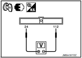
6.CHECK ECM POWER SUPPLY CIRCUIT-II

- Turn ignition switch OFF and wait at least 10 seconds.
- Check the voltage between ECM harness connectors.

7.CHECK ECM POWER SUPPLY CIRCUIT-III

- Turn ignition switch ON.
- Check the voltage between IPDM E/R harness connector and ground.

8.CHECK INTERMITTENT INCIDENT
9.CHECK ECM POWER SUPPLY CIRCUIT-IV
- Turn ignition switch OFF and wait at least 10 seconds.
- Check the voltage between ECM harness connectors.

10.CHECK ECM POWER SUPPLY CIRCUIT-V
- Disconnect ECM harness connector.
- Disconnect IPDM E/R harness connector.
- Check the continuity between ECM harness connector and IPDM E/R harness connector.
- Also check harness for short to ground and short to power.

11.CHECK 15 A FUSE
- Disconnect 15 A fuse (No. 42) from IPDM E/R.
- Check 15 A fuse.
12.CHECK ECM POWER SUPPLY CIRCUIT-VI
- Disconnect ECM harness connector.
- Disconnect IPDM E/R harness connector.
- Check the continuity between ECM harness connector and IPDM E/R harness connector.
- Also check harness for short to ground and short to power.

13.DETECT MALFUNCTIONING PART
Check the following.
- Junction block connectors E44, E45
- Harness for open or short between ECM and IPDM E/R
14.CHECK INTERMITTENT INCIDENT
 Trouble diagnosis - specification value
Description
The specification (SP) value indicates the tolerance of the value that is
displayed in "SPEC" of "DATA MONITOR"
mode of CONSULT during normal operation of the Engine Control System. W ...
 U0101 can comm circuit
Description
CAN (Controller Area Network) is a serial communication line for real time
application. It is an on-vehicle multiplex
communication line with high data communication speed and excelle ...
Other materials:
P1740 select solenoid
Description
The lock-up select solenoid valve controls
lock-up clutch pressure or forward clutch pressure (reverse brake
pressure).
When controlling lock-up clutch, the valve is
turned OFF. When controlling forward clutch, it is turned ON.
DTC Logic
DTC DET ...
Remote starting the vehicle
To use the remote start feature to start the engine
perform the following:
1. Aim the Intelligent Key at the vehicle.
2. Press the LOCK button to lock
all
doors.
3. Within 5 seconds press and hold the
remote start button until the turn signal lights
flash and the tail lamps turn on. ...
System description
HEATED STEERING WHEEL
System Diagram
System Description
The heated steering wheel switch controls the heated steering relay. When the
switch is turned on, the relay is energized and the heated steering system
will operate. The heated steering system will turn off when the steering
wheel ...
Nissan Maxima Owners Manual
- Illustrated table of contents
- Safety-Seats, seat belts and supplemental restraint system
- Instruments and controls
- Pre-driving checks and adjustments
- Monitor, climate, audio, phone and voice recognition systems
- Starting and driving
- In case of emergency
- Appearance and care
- Do-it-yourself
- Maintenance and schedules
- Technical and consumer information
Nissan Maxima Service and Repair Manual

0.0063