Nissan Maxima Service and Repair Manual: P0615 starter relay
Description
- TCM controls starter relay in IPDM E/R.
- TCM switches starter relay ON at "P" or "N" position and allows to crank engine.
- Then it prohibits cranking other than at "P" or "N" position.
DTC Logic
DTC DETECTION LOGIC

DTC CONFIRMATION PROCEDURE
CAUTION: Always drive vehicle at a safe speed.
NOTE: Immediately after performing any "DTC CONFIRMATION PROCEDURE", always turn ignition switch OFF.
Then wait at least 10 seconds before performing the next test.
1.CHECK DTC DETECTION
 With CONSULT
- Turn ignition switch ON.
- Perform "Self Diagnostic Results" in "TRANSMISSION".
Diagnosis Procedure
Regarding Wiring Diagram information, refer to TM-126, "Wiring Diagram".
1.CHECK STARTER RELAY SIGNAL
- Turn ignition switch ON.
- Disconnect IPDM E/R connector.
- Check voltage between IPDM E/R vehicle side harness connector terminal and ground.


2.CHECK HARNESS BETWEEN TCM AND IPDM E/R (PART 1)
- Turn ignition switch OFF.
- Disconnect TCM connector.
- Check continuity between TCM vehicle side harness connector terminal and IPDM E/R vehicle side harness connector terminal.


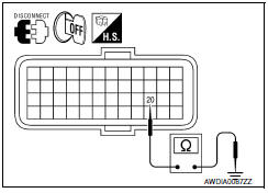
3.CHECK HARNESS BETWEEN TCM AND IPDM E/R (PART 2)
Check continuity between TCM vehicle side harness connector terminal and ground.

4.DETECT MALFUNCTIONING ITEMS
Check TCM connector pin terminals for damage or loose connection with harness connector.
 U1010 control unit (CAN)
Description
CAN (Controller Area Network) is a serial communication line for real time
application. It is an on-vehicle multiplex
communication line with high data communication speed and excelle ...
 P0703 brake switch B
Description
BCM detects ON/OFF state of the stop lamp switch and transmits the data to
the TCM via CAN communication
by converting the data to a signal.
DTC Logic
DTC DETECTION LOGIC
DTC CON ...
Other materials:
Precaution
PRECAUTIONS
Precaution for Supplemental Restraint System (SRS) "AIR
BAG" and "SEAT BELT
PRE-TENSIONER"
The Supplemental Restraint System such as "AIR BAG" and
"SEAT BELT PRE-TENSIONER", used along
with a front seat belt, helps to reduce the risk or severity of injury to the
driver and fr ...
The parking brake release warning continues displaying, or does not display
Description
The parking brake warning is displayed while
driving the vehicle even though the parking brake is released.
The parking brake warning is not displayed even
though driving the vehicle with the parking brake
depressed.
Diagnosis Procedure
1.CHECK ...
P0171, P0174 fuel injection system function
DTC Logic
DTC DETECTION LOGIC
With the Air/Fuel Mixture Ratio Self-Learning Control, the actual mixture
ratio can be brought closely to the
theoretical mixture ratio based on the mixture ratio feedback signal from A/F
sensor 1. The ECM calculates
the necessary compensation to correct the o ...
Nissan Maxima Owners Manual
- Illustrated table of contents
- Safety-Seats, seat belts and supplemental restraint system
- Instruments and controls
- Pre-driving checks and adjustments
- Monitor, climate, audio, phone and voice recognition systems
- Starting and driving
- In case of emergency
- Appearance and care
- Do-it-yourself
- Maintenance and schedules
- Technical and consumer information
Nissan Maxima Service and Repair Manual

0.0062